


Version 2026.5
Topic Links
(use your browser’s “back” button to return to this section after clicking a link)
General Terminology User Interface Quick Start
Emitter Libraries Browsing Search Locked vs. Unlocked Favorites
Create Blank Emitter Library Scenes Add Emitter to Library Save Scene to Library
Emitter: Parameters, Properties, Position, Shapes, 3D Models
Turbulence Legacy Interpolation
Super Emitters Free Emitters Make Super Emitter
Particle Color/Alpha Particle Parameters & Properties Lines/Trails
Particle Sprites/Images Importing from File Generating with AI
Copying Particle Gradients and Sprites/Images Parameter Linking
Deflectors Forces Fluid Dynamics
PI Camera Camera Presets Composite View (Stage) Widgets Toolbar
Controls View Emphasized & De-emphasized Parameters Parameter Search
Nodes View Soloing Disabling Nodes
Graph View Animating Parameters Over Life Graphs
Project Settings Preferences Reset Prefs Rendering
File Locations Keyboard Shortcuts Diagnostics Log File
Mocha Tracking Particle Masking Compositing Modes AE Camera
Glow Beat Reactor AE Path/Light/3D Layer Follow AE Text Trace
Video Import Mocha Pro/SynthEyes Data
Over Life Graph Presets Position Path Presets Transform Position Path
Scale Animation Timing Equalize Path Timing Repeat Animation Reverse Animation
Particle Illusion Overview
Introduced with Continuum 2019, Particle Illusion is a sprite (image) based particle effect system that is preset driven, easy to use, and powerful. A 64-bit update of the original particleIllusion from the early 2000’s, a new UI, reorganized libraries, and thousands of curated presets bring exciting particle effects to artists and editors of any skill level. The addition of Mocha tracking, masking, and transfer modes makes integrating advanced particle effects into your work easier than ever.
Advanced features have been added in recent releases, such as 3D particles with integrated camera, Fluid Dynamics, 3D model emission, 3D deflectors, particle trails, and more.
Note that Particle Illusion is available as a standalone application and also as a plugin. Some features are only applicable to the plugin version — they will be noted throughout these documents.
Important: There are just 2-3 libraries installed with Particle Illusion: the “Sampler” library, the “Emitters_2026.5” library of new emitters for this release, and an editable “Custom” library (if you don’t have a “Custom” library installed already). To get the full set of additional emitter libraries use the “Download Emitters” option from the “Help” menu:
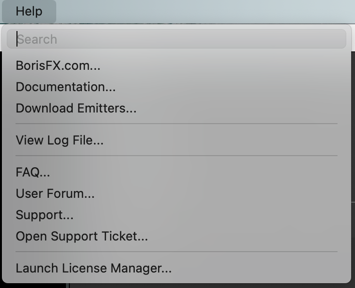
This requires a connection to the Internet, and will require you to login with your BorisFX account, or register for a free account.
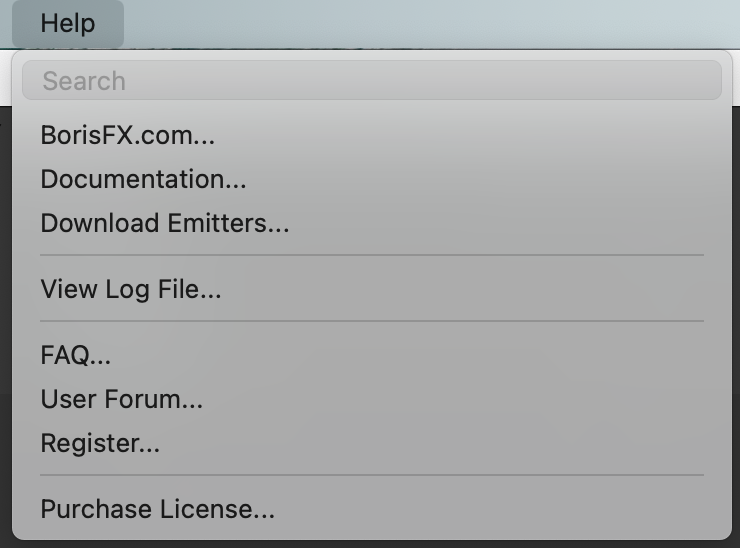
If you’re running Particle Illusion without a license, your Help menu will look slightly different:
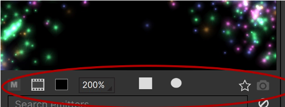
Particle Illusion will let you know if you haven’t installed the additional libraries by showing a red warning icon above the Library Browser - hover over it for more information:
![]()
Also note that if you’ve already installed these additional libraries from the previous version of Continuum (or Particle Illusion Standalone), then you don’t need to install them again — the newest emitter library is always included with the main Continuum or Particle Illusion installer.
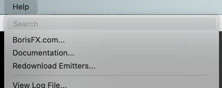
Finally, If the additional libraries are already installed the Help menu will show “Redownload” instead of “Download”:
Particle Effects Terminology
If you’ve not used particle effects before, or if you’re new to Particle Illusion — often referred to as “PI” in these docs — a quick look at the terminology will be helpful in understanding the rest of the documentation and tutorials.
Particles: Particles are the visible entities in Particle Illusion. You have no direct control over individual particles; once they are “born” they behave based on the values set in their Particle Type. Particles use images for their appearance.
Particle Type: A particle type is the collection of properties that determine how particles of this type look and behave. A particle type consists of image(s) (also known as “sprites”), a color gradient, and various properties such as velocity, size, weight, etc.
Emitters: An emitter is not visible, but is the object that creates particles. Emitters come in 4 shapes types: point, line, ellipse (circle), and area. An emitter contains one or more particle types, and “global” duplicates of many of the particle type properties (velocity, size, etc.). Emitters, unlike particles, can be directly controlled and moved over time.
So an emitter is made up of particle types, and particle types are made from images, and particles are created by the emitter based on the properties of its particle types. In other words, an emitter creates particles which combine to form the visual effect.
A more complex type of emitter is a “super emitter”.
Super Emitters: This is a special type of emitter in Particle Illusion that does not create particles directly, but creates other emitters which in turn create the particles.
Free Emitters: The emitters that a super emitter creates. They are similar to particles in that you cannot directly control their position — once they are “born” they behave based on the properties of their Free Emitter Type.
Free Emitter Type: Like a Particle Type, this is the collection of properties that determine how the free emitters of this type will behave.
So a super emitter is made up of free emitter types and free emitters are created by the super emitter based on the properties of its free emitter type. Each free emitter type consists of particle types, and particles are created by each free emitter based on the properties of its particle type. In other words, a super emitter creates free emitters, which in turn create particles which combine to form the visual effect.
Emitter Library: a collection of emitter “presets” saved as a single file. This is not really important in Particle Illusion unless you want to copy or move libraries — to share them as an example. Note that once an emitter is added to a project it is completely independent of that library.
These Emitter Library emitters are the starting point for building new particle effects: the first step in building an animation is to add one or more emitters from the Emitter Library to your project.
Starting with the 2022 release, Libraries can now also store “Scenes” — essentially complete projects. Multiple emitters, forces, deflectors can all be saved in a Library Scene, and unlike with library emitters, Scenes save position animation too.
Navigating the Particle Illusion User Interface
In this section we will introduce the five primary views used in Particle Illusion to select, modify, animate, and preview effects.

- Emitter Library Browser
The Emitter Library browser displays every emitter library and emitter available. Manually browse the thousands of available emitters or use the emitter search to help you zero in on the effect you’re looking for. Choose from a Library View (shown), List View, or Grid View of larger icons for more visual browsing. - Emitter Preview
A live view that displays the emitter selected in the Emitter Library Browser. Click and drag in this view to see how the selected effect will behave before adding it to your project. More on the Emitter Preview below. - Composite View (or “Stage”)
The Composite view displays the composited effect as it will appear in your final output. Click to add the selected library emitter to the project, then adjust the emitter position by dragging if needed. It also offers menu options that adjust some preview settings while you work, such as zoom level, background image preview, and H.U.D. (on-screen overlays). Also known as the “Stage” if you’re an original particleIllusion user. - Controls View
The Controls view displays the properties and animatable parameters for each emitter. The Controls view allows you to adjust the values for each parameter and choose how to interpolate those values between keyframes. - Graph View
The graph view gives you a wide range of controls that allow you to animate parameter attributes in the timeline by setting keyframes. A keyframe sets specific parameter values for a parameter at a certain point on the timeline. When you place multiple keyframes on the timeline, PI interpolates, or computes intermediate values, between keyframe values to animate the effect. Keyframes will be covered in detail in a future tutorial. - Nodes View (or “Node Graph”)
The node view shows the emitters, forces, and deflectors that are in the project, allowing easier navigation of the parameters in the controls view. The particle types of each emitter are also shown, giving a much clearer picture of the components of each effect.
Emitter Preview
When browsing emitters, the Emitter Preview (or “Preview”) will show the selected emitter. This is a live window that you can click and drag in to see how the particles behave when moving (unless a “Scene” is selected, which only displays the thumbnail in the Preview – more details in the section on Library Scenes).
There are a few controls below the preview, which will be described here. From left to right…
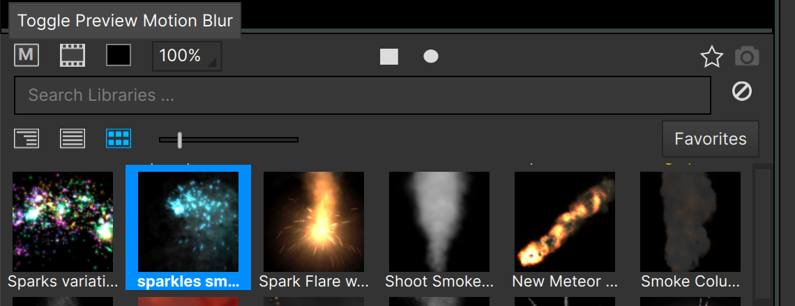
Motion Blur: When turned on the particles will be drawn with motion blur. This can enhance realism, especially for fast-moving particles. Note that emitters that have “(mb)” in their names were designed to be used with motion blur.
Background Image: When on the background will be an image instead of a solid color. Useful for some effects, especially if they get their colors from the source layer. (Particles can get their colors from source only in the plugin version). Note that selecting an emitter that gets its color from the source will use this image automatically for the particles regardless of the setting of this option.
Background Color: Although many particles look best when shown on a black background, some need a lighter color to display correctly (this is often indicated in the thumbnail image for the emitter with a grey or white background). Use this to set the background to any color.
Zoom Level: Controls the zoom level of the preview. Note that this is for display only — it does not modify the settings in the emitters.
Play/Stop Button: This control is in the center of the toolbar and allows you to stop (pause) the preview. Although you usually won’t want to do this, it can be useful when examining an effect or to set the emitter thumbnail image.
Record Emitter Position Button: This allows you to record and playback movement in the preview. Click this button to turn it red, then click and drag around the preview. When you release the mouse button playback will automatically start and continue until you click this button again to stop it. This allows you to select and preview different emitters without needing to manually drag around the preview each time.
Favorites: Click this star icon to add the selected emitter to your “favorites” collection. When selecting an emitter that is already a “favorite”, this icon will be highlighted.
Update Thumbnail: When an emitter in an unlocked library (details later on locked vs. unlocked libraries) is selected, this icon will be enabled. Clicking it will update the thumbnail image for the emitter based on what’s visible in the preview. (Note that it is not possible to update the thumbnail of Library Scenes.)
Browsing Emitters
There are a few different ways to browse the dozens of different emitter libraries in Particle Illusion, including with an emitter search:
Type a term in the search bar to filter the emitters that are displayed. (This will be covered in more detail later in this document.)
Below the emitter search field there are three icons — these control the type of view used for the emitters: Library View, List View, and Grid View.
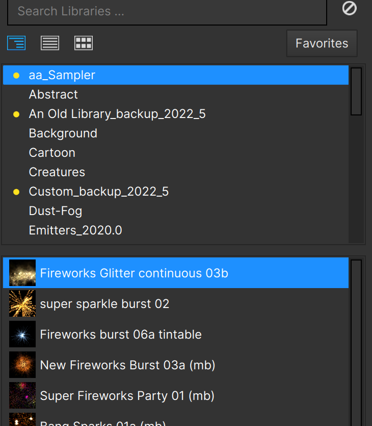
Library View displays the emitters in a split view, showing the libraries in the upper pane and the emitters in the selected library below.
(The Library View replaces the older Tree View, and requires much less scrolling and twirling open/closed to navigate.)
List View shows more information about each emitter in a flat list:

Note that the heading of each column can be clicked to sort — clicking toggles between A-Z, Z-A, and unsorted. (The default is unsorted.)
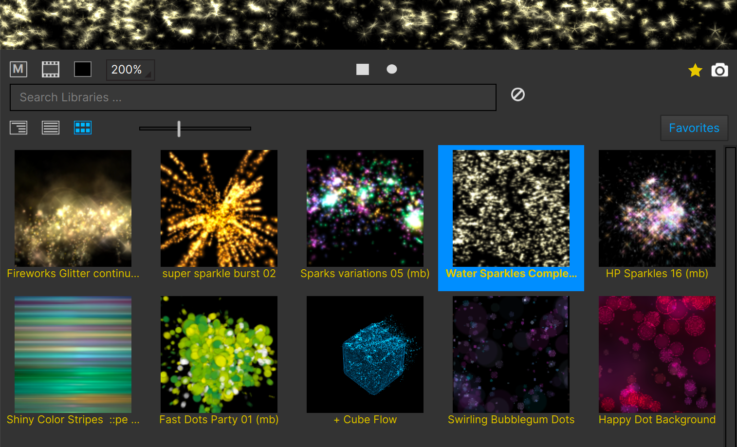
Grid View shows the thumbnails and emitter names only:

This is the most visual way to browse the emitters. Note that when in grid view a slider appears above the top row of emitter thumbnails that allows you to select the size of the thumbnails.
Favorites
The emitters that you have flagged as “favorites” are designated in two ways. In each view if the selected emitter is in your favorites collection, the star icon below the preview will be highlighted:

Also, the emitters that are flagged as “Favorites” will have their names drawn in the gold color of the star icon:

Also, you will see a “Favorites” button at the right below the search field. When clicked, only the emitters in the “favorites” collection will be displayed:
Library Scenes
Scenes are similar to emitters in a library in that they both are a type of preset, both have thumbnail images, and both are added to the project in the same way. There are significant differences though:
- Scenes have a “+” symbol before their name
- Scenes only show their thumbnail image in the preview — it is not a live preview
- Scenes can contain multiple emitters, forces, and deflectors. (It is this complexity that requires the removal of the live preview)
- Scenes preserve position data, so are always added at absolute positions (you can’t click to add a Scene at a different position in the Stage)
- Scenes save layer position and angle data (starting in v2026.5), so existing layer data can be replaced by layer data from a scene.
Missing Libraries Warning
If you see a red warning icon in the Library Browser toolbar, this means that you are missing quite a few libraries:
![]()
Unless you’ve deleted them on purpose, you’ll want to click on that icon to download the additional emitter libraries installer.
Quick Start: Adding An Emitter Basics
1) Select an emitter. Either browse the libraries or use the emitter search to find the type of particle emitter that you’ll want to use in your project. If you can’t find exactly what you’re looking for, select something that is close, as you’ll be able to modify all aspects of it later.
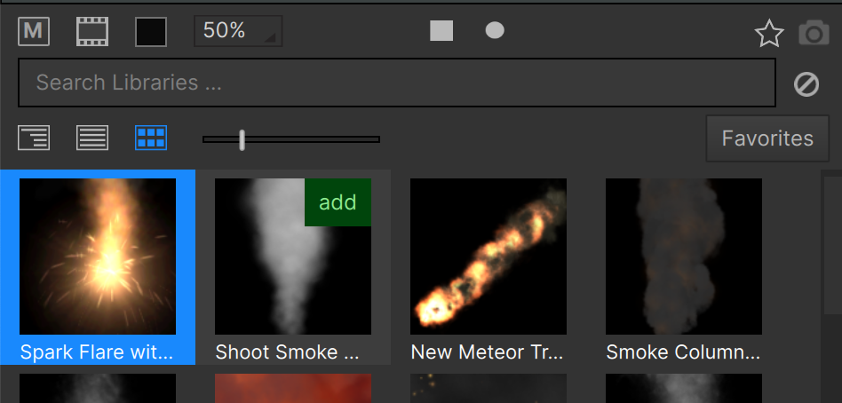
2) Click the “Add” button that shows when you hover over the preset — this will add the emitter to the center of the Stage. You can also double-click the preset or Alt/Option-click the emitter to add it to the Stage, and there is a Preference called “click to add emitter” that when checked will allow you to click in the Stage to add the selected emitter at the click location (but it is disabled by default).
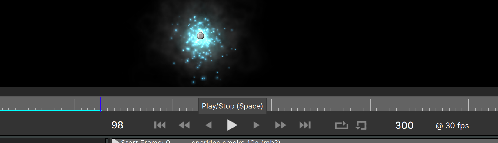
3) Press Spacebar to toggle playback in the Stage.
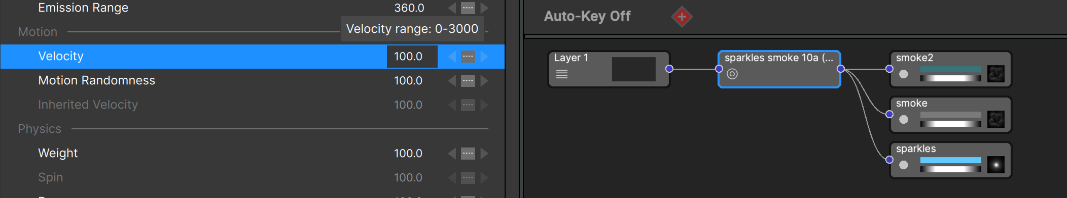
4) Adjust parameters. In the Controls View select the appropriate parameter and adjust its value as needed. Experimenting is encouraged. (Tip: if you want to make the entire effect bigger, use the “Zoom” parameter instead of “Size”):
5) Load a position path preset, or manually animate position (optional). To load a preset, r-click the “Position” parameter and select “Load Preset” – or with the “Position” parameter selected click the “Load” button that shows under the graph view.
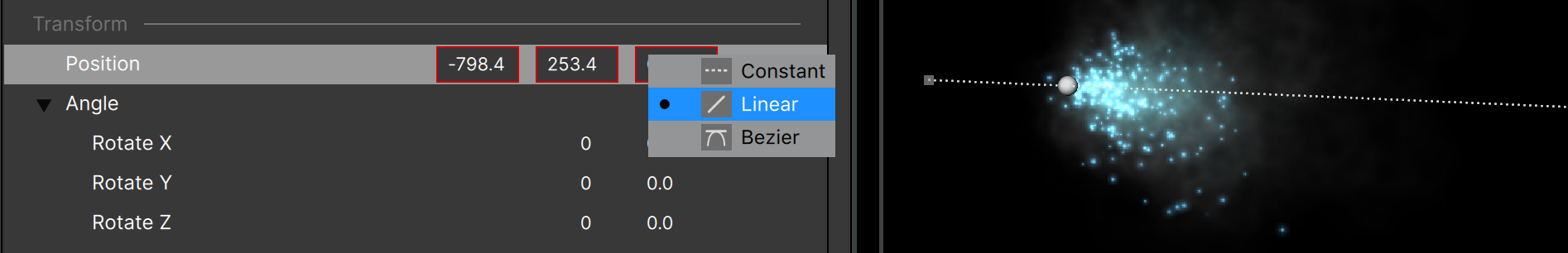
To manually animate position, select the “Position” parameter and click the “Add Key” button at the left side of the playback toolbar. Then jump ahead in time and drag the emitter in the Stage to it’s new position - a new key will automatically be added. Note that the position values in the Controls View are drawn with a red box — this indicates they are animated:
6) Click “Apply” to close and return to the host application (The “Apply” button is only visible when running as a plug-in.)
Alternately, render directly from Particle Illusion by clicking the “Render” button found below the Stage to the right of the playback toolbar:

That’s all that is required to add a Particle Illusion effect!
Project Files
Whether you are running Particle Illusion as a plug-in (from a host application) or standalone, you can save or load Particle Illusion project files at any time. This allows you to save works-in-progress or different versions of your work. Note that saving a project file is not required when running as a plug-in, but it can still be a useful feature — especially to save backup copies outside of your host application project.
To save a project use the File – Save Project menu item, or the Cmd/Ctrl S keyboard shortcut.
A project file can be loaded at any time, even when you’re running as a plug-in. Use the File – Open Project menu item, or the Cmd/Ctrl O shortcut.
Note that the project file contains Stage Settings such as resolution, framerate, and pixel aspect ratio, although when running as a plugin these values are set by the host and can’t be changed in Particle Illusion.
Rendering
It’s possible to render a movie file directly from Particle Illusion. This could be much faster than rendering back in the host , especially with complex particle setups and compositions that have many other layers. Once the design of the particles is completed, you can then replace your Particle Illusion layer with the rendered file as footage.
To render a movie file, click the “render” button at the right side of the playback bar:

…and the render settings window will open:
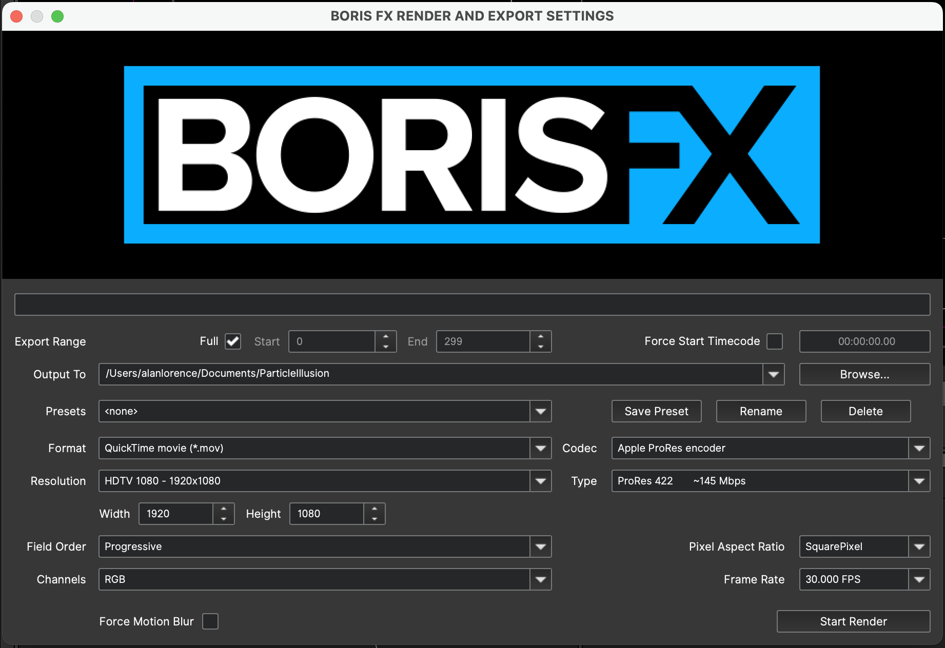
Here you will be able to choose the range of frames to render, the output filename and path, output format, resolution, framerate and more.
There are two output formats to choose from: MP4 and ProRes.
ProRes is the preferred format, as it’s the only way to embed an alpha channel into the video — select one of the ProRes Presets that contain alpha. (With MP4 you must render the RGB and Alpha as two separate files.)
Note that changing the render Resolution, Pixel Aspect Ratio, and Frame Rate from what is in your Project Settings may produce unpredictable results.
Nodes View
Before looking at the parameters in the Controls View, remember from earlier that a regular emitter is made up of one or more particle types, and a super emitter is made up of one or more free emitter types, which in turn contain one or more particle types. This relationship is clearly seen in the Nodes View:

The Nodes View (or “Node Graph”) is how you’ll navigate your Particle Illusion project – select any node to see its parameters in the Controls View.
There are a few aspects of nodes that will speed up your workflow, the main being context menus. R-Click on a node to bring up the “hamburger menu” (before v2023.5 only available in the Controls View “hamburger” menu):

This is a quick way to disable a node, duplicate it, rename, etc.
There are shortcuts to some of these functions that doesn’t require you to open the menu first:
“Rename/Notes”: Double-click on the node name
“Disable/Enable”: Double-click on the node icon
“Solo/Unsolo”: Alt-double-click on the node icon (Option-double-click on Mac)
*Note: To temporarily solo any node, click and hold on the node icon. The node will be soloed while the mouse is held, and will be unsoloed upon release.*
For particle nodes you can also double-click on the color or alpha gradient to edit it, or double-click the shape image to open the Particle Shape Editor.
Some nodes will have a yellow “info” icon showing:
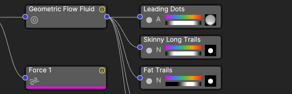
This indicates that this node includes a Note: helpful information about usage, important parameters, or ways to create variations – anything useful to getting the most out of the effect.
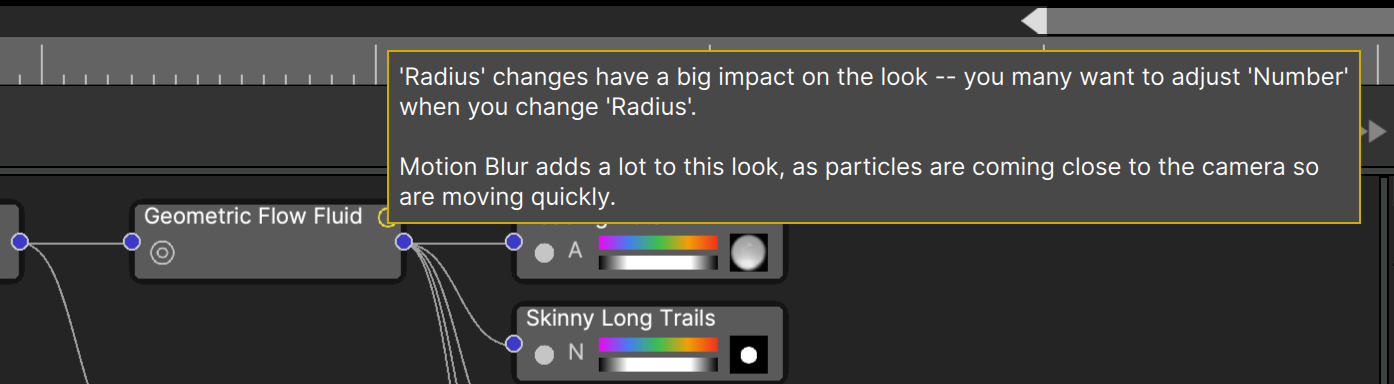
Hovering the cursor over the icon displays the note in a tooltip:
Open the “Rename/Note” dialog to view or edit the note:
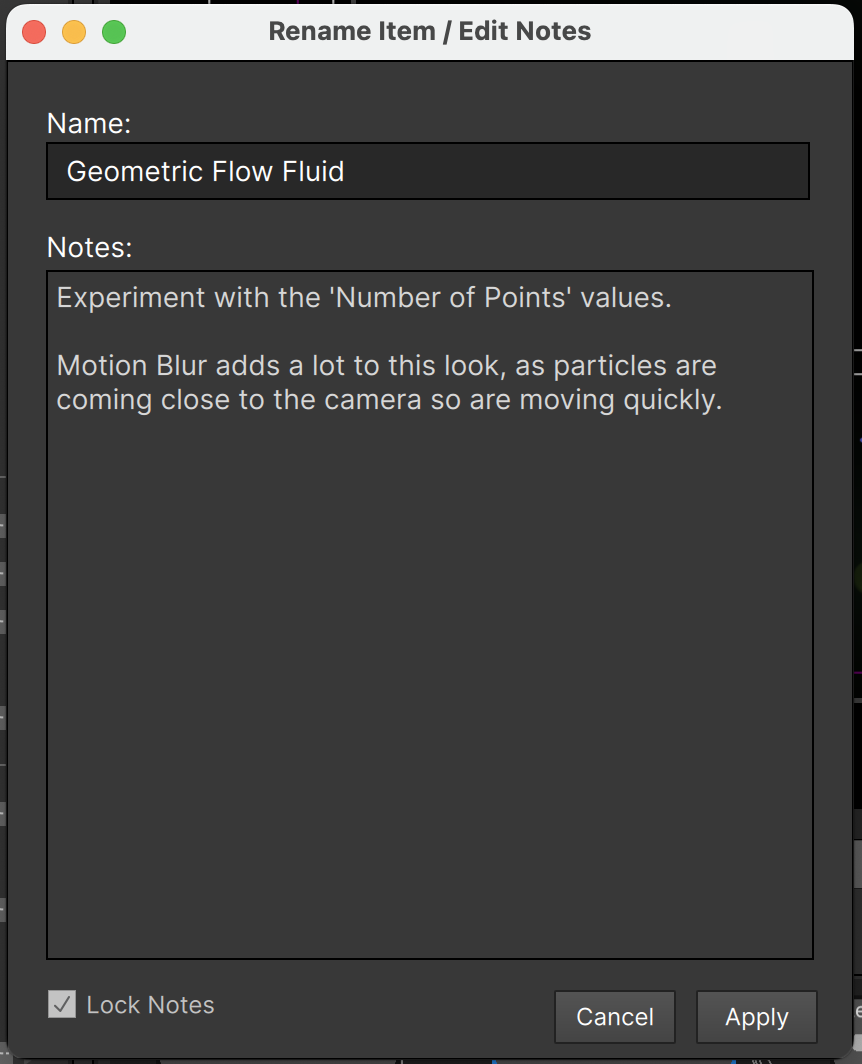
The dialog opens with the note locked to prevent inadvertent changes; unlock and edit as desired.
There is no real limit to the size of the note you can add – Notes can even include emojis!
Note tooltips can help you understand what’s going on in that node, and for particle nodes there is another helpful tooltip available: sprites (particle shape images)
Just click and hold on the sprite thumbnail on the node, and a larger version of the image will display:
![]()
This popup displays other information about the image too, and will even auto-animate if there are multiple frames.
Soloing Nodes
When a node is soloed, it displays with a white bar:
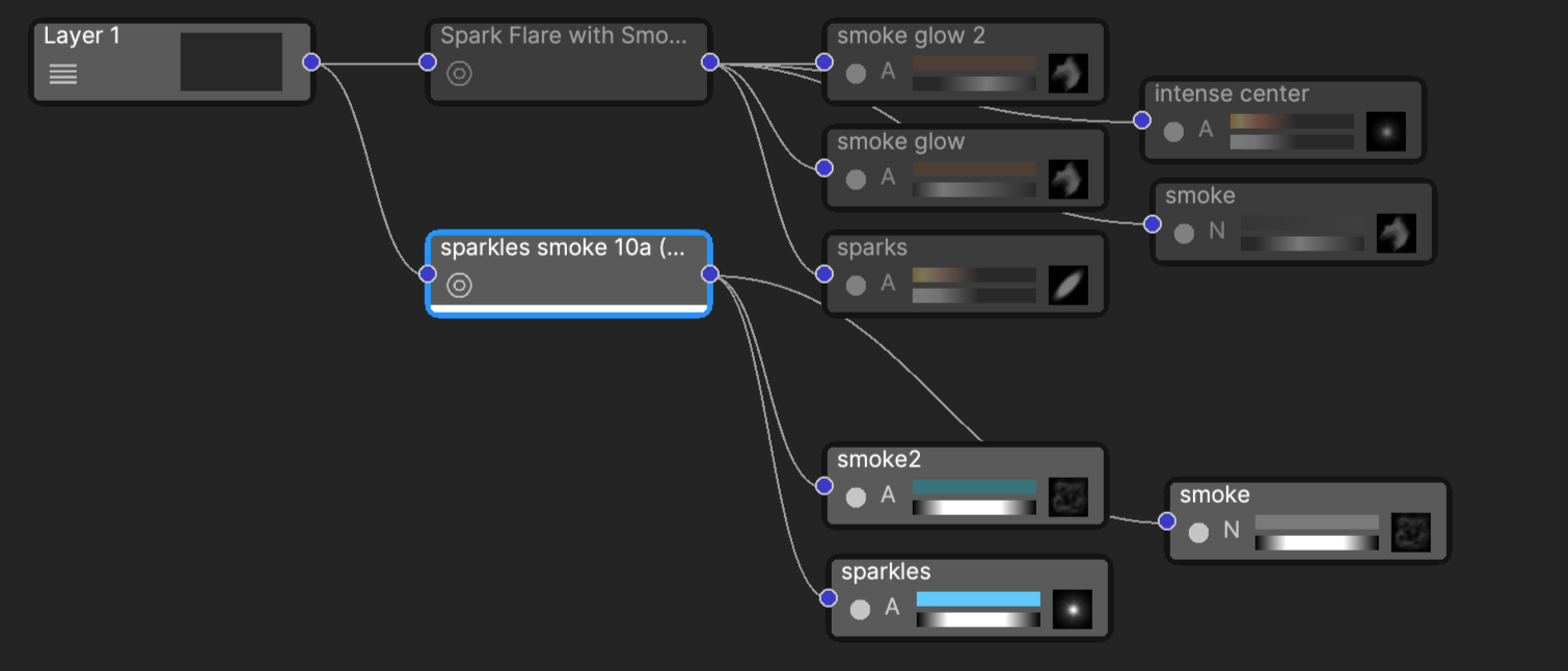
In addition, all other non-related nodes are disabled. The results will vary based on what type of node is soloed, for instance when a particle node is soloed its parent nodes must stay enabled:

Soloing nodes is a great way to identify specific emitters or particles in a complex project.
Note that only a single node can be soloed at a time. If you want to see more than one node “soloed”, solo one and then you can still enable any of the other nodes.
Also it’s not necessary to unsolo a soloed node before soloing another. If you solo a particle node and then realize you want to solo a different one, just solo it. The previously soloed node will unsolo automatically (since only one node can be soloed at a time).
*Note: To temporarily solo any node, click and hold on the node icon. The node will be soloed while the mouse is held, and will be unsoloed upon release.*
Emitter Parameters
The Controls View shows the parameters for the selected node: emitter, particle type, etc. Since many of the parameters at each level have the same names — for instance you’ll see “Velocity” at the emitter level, free emitter type level, and particle type level — it’s important to know the difference between them.
Let’s take a closer look at each of the parameters in the Controls View when an emitter is selected:
We’ll skip the “Properties” group for now, so we’ve closed it (it will be opened by default).
Starting with v2023, the parameters are grouped according to function: Appearance, Transform, Emission, etc.
It’s important to remember that the values for most parameters at the Emitter level are scaling factors applied to the parameters of the same name in the particle nodes. More on this in the section on parameter de-emphasis later.
Most of these should be self explanatory, but we’ll go over each of them to be thorough:
“Size”: The scale factor for all child particle sizes. Only controls the size of the particles, not their motion.
“Zoom”: Scales the size and the movement of particles so that the entire effect appears to change scale – zoom in or zoom out. Does not affect line thickness or 3D model scale. In 3D projects the same result can be had by changing the distance between the emitter and the camera or by changing camera settings.
“Opacity”: Scales the opacity (visiblity) of all child particles. Does not affect 3D model wireframe opacity or lines that have “Line Opacity Type” set to “Specify”.
“Tint Color”: Although particles have their own “Color over life” gradients, this can be used to modify or override those colors.
“Tint Strength” controls the amount of tint color applied, and is used in conjunction with the Tint Color. A value of 100 will completely override the particle colors, while when set to 0 the Tint Color has no effect.
“Position”: the emitter position, which can be controlled here or in the Composite View (Stage) directly. Note that when in 2D mode there will be only 2 parameters here (X/Y), but in 3D mode there will be 3 as shown (X/Y/Z).
“Angle”: used to rotate line, area, plane, box, sphere and ellipse emitters, and in many cases will have no visible effect on point emitters (or circle emitters in a 2D project).
“Life”: The scale factor for all child particle “life” values, how long particles are alive.
“Number”: The scale factor controlling how many particles are created. If this is set too high when you change the Emitter “Shape” or the dimensions of a shaped emitter, a huge number of particles may be created.
“Emission Angle”: When “Emission Range” is less than 360 (degrees), this sets the direction of particle emission. For Point emitters “Emission Angle” is relative to “Angle”. For Line, Circle, Sphere, and Ellipse emitters 0 degrees is along the emitter, with 90 degrees being perpendicular. Can be unpredictable when emitter shape is “3D Model”.
“Emission Range”: The “spread” of particles. When set to “0.0” (degrees) all particles emit at the same angle (in a line). When set to “30.0” a 30-degree cone of particles will be emitted, and larger values widen the “cone”.
(Note that in 2D mode the “Emission Angle” and “Angle” parameters become a single value.)
“Velocity”: Scale factor for all child particle velocities, the rate of motion along a straight line. (Probably should have been named “Speed” since it’s a scalar and not a vector)
“Motion Randomness”: Scale factor for all child particle motion randomness, a “wandering” type of motion.
“Inherited Velocity”: Scale factor for all child particle inherited velocities, the amount of motion a particle gets from its moving parent emitter.
“Weight”: Scale factor for all child particle weight, which determines if particles rise or fall (gravity).
“Spin”: Scale factor for all child particle spin values.
“Bounce”: Scale factor for all child particle bounce values.
“Affect Fluids”: Determines how much the child particles (and free emitters if a super emitter) will impart motion to the fluids. Requires a force object with fluid dynamics enabled.
“Affected by Fluids”: Determines how much the movement of fluids affects the child particles (and free emitters).
“Position Turbulence”: Scale factor for all child particle position turbulence, the amount the particle’s position is offset by the noise function (see below).
“Size Turbulence”: Scale factor for all child particle size turbulence, the amount the particle’s size is affected by the noise function (see below).
More details about some of these parameters in the Particle Parameter section below.
Parameter Search
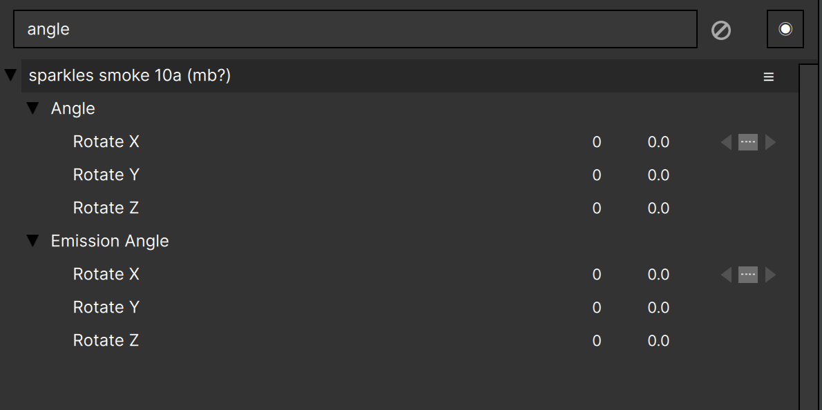
There are a large number of different parameters in Particle Illusion, especially when a particle node is selected. To help you find the parameters that you’re looking for, there is a parameter search at the top of the controls view:
Type here to filter the parameter list, either showing only the parameters that match the search, or by highlighting them in the full parameter list, depending on the state of the “Show All Parameters” button to the right of the search. With Show All Parameters off:
And with Show All Parameters on:
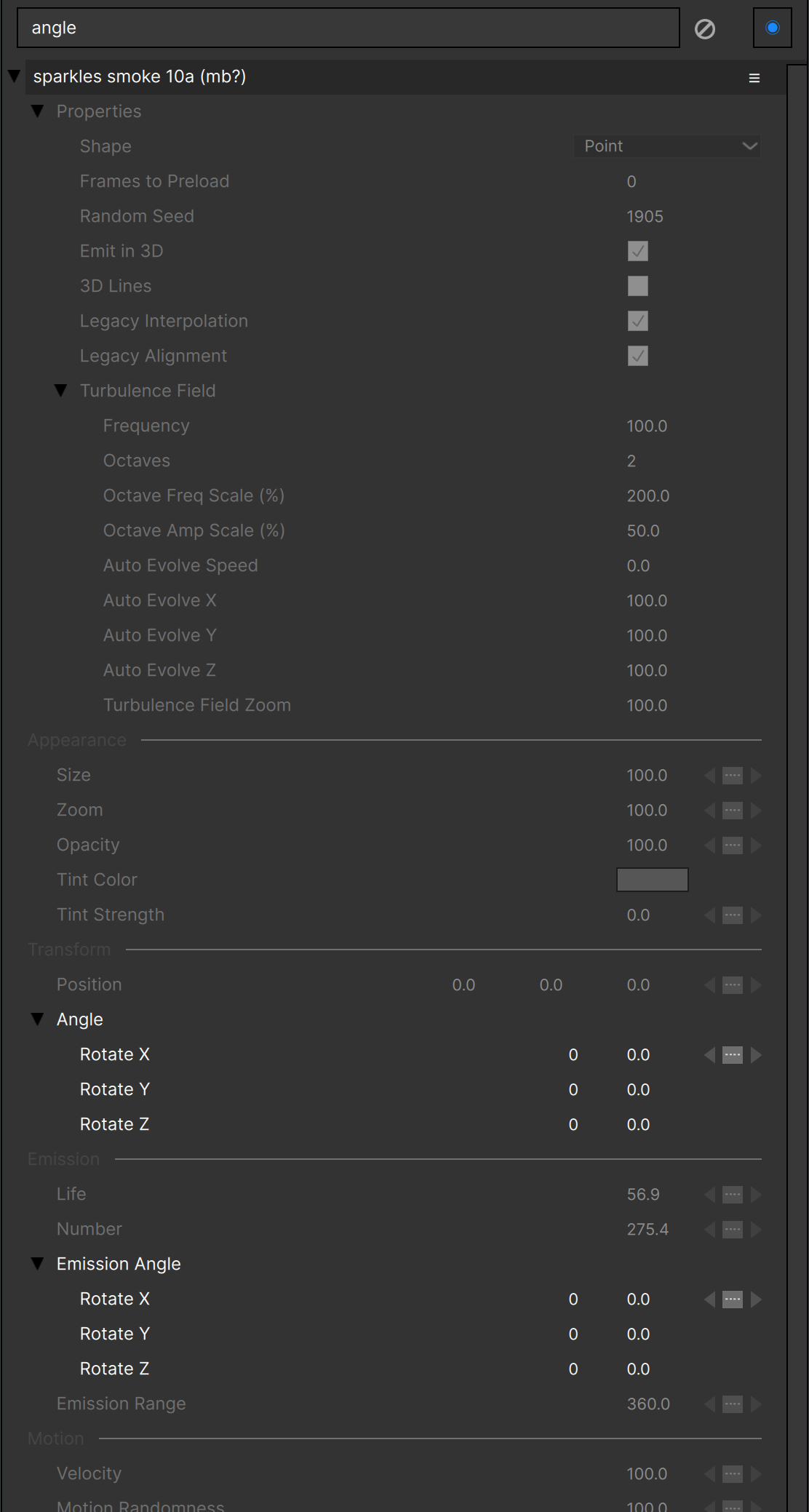
Parameter search can be very helpful, especially when you are new to Particle Illusion and haven’t yet learned where specific parameters are found in the list.
3D Particles
Although the particles themselves are still always 2D sprites, it is possible to have them emit in a 3D environment.
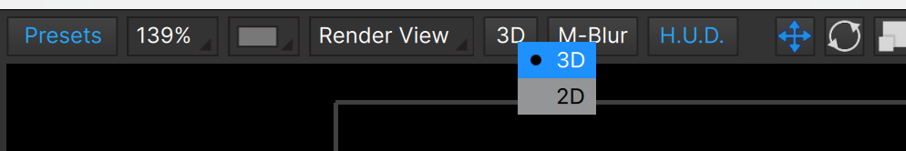
To enable 3D, toggle the 2D/3D selector above the stage to “3D”, which is the default setting:
Once in 3D mode, any emitters that are added to the stage will be set to emit in 3D. If you already had emitters in the project before you switched to 3D, you can manually set those to emit in 3D in the emitter “Properties” section:
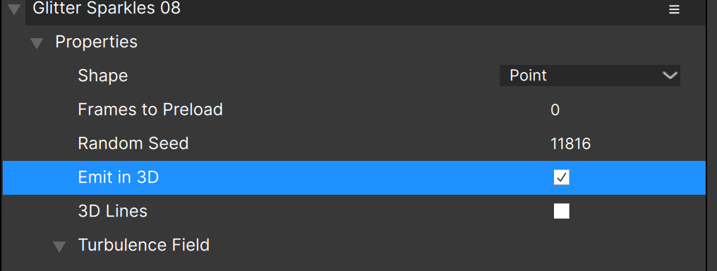
Similarly there may be a reason that you’d want to keep an emitter in 2D inside a 3D project — you can do this by unchecking the “Emit in 3D” option.
Camera
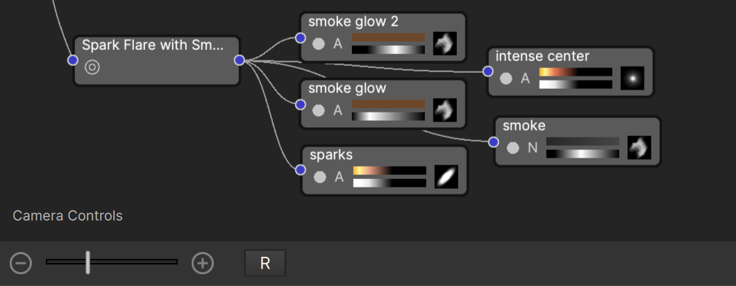
To actually see any result of this switch to 3D particle emission, you need to have multiple emitters at different depths (z-coordinates), or add some camera motion: for that you need to select a camera model. To show the camera parameters, click in the Nodes View in an empty area (no node(s) selected) or on the “Camera Controls” text in the lower left corner:
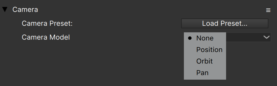
The Camera parameters will then display in the Controls View:
Note: The easiest way to use the Particle Illusion camera is to load a [camera preset](#camera_presets).
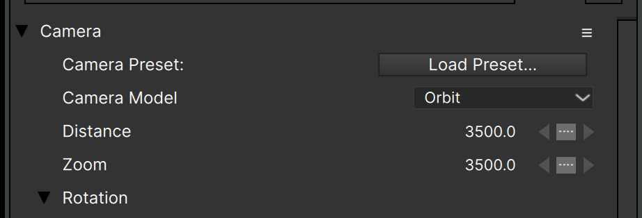
The camera model defaults to “None”, but there are three other options: Position, Orbit, and Pan.
In brief…
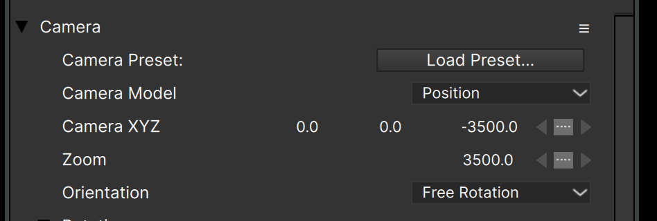
Position: has the most controls and is most complex, but gives you all of the options you’d need, including the ability to always point at a specific point or object (emitter).
Orbit: A simplified camera that always points at the origin (0,0,0), useful for easy orbiting of an emitter or scene.
Pan: Simplified camera that is used to pan horizontally.
We’ll look at each of these models In more detail below, but first…
Real-World Equivalents
When working with the Particle Illusion camera you may wonder how to get the focal length equivalent (18mm, 35mm, 200mm etc.) when there is no obvious parameter for this.
It’s actually simple : just set both the “Distance” and “Zoom” parameters to 100x whatever focal length you want. For example, the following values give you a 35mm equivalent:
Note that if you’re using a camera model that does not have a “Distance” parameter, you’ll use the Z value or whatever is appropriate to make the calculated distance correct. For instance:
(Note that very long focal lengths may not work with lower project resolutions.)
Position Camera Model
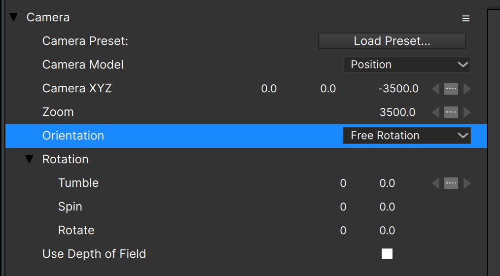
With the Position camera model and the “Orientation” set to “Free Rotation”, you have a camera that can be animated with no restrictions: you set the camera position, and its orientation in 3D space.
Use Tumble to rotate the camera around its X axis, Spin to rotate it around its Z axis, and Rotate for the Y axis.
Note that rotating the camera when in “Free Rotation” orientation can make it difficult to track what the camera is pointing at.
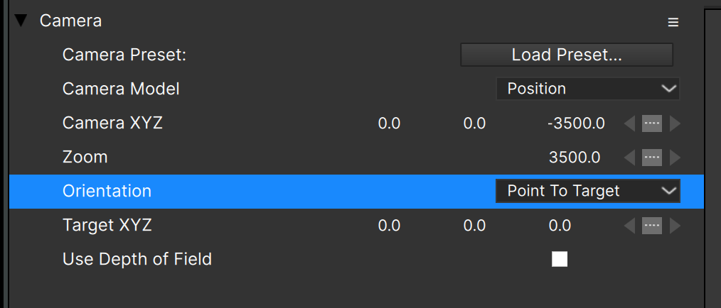
When Orientation is set to “Point to Target”, you set the XYZ coordinates of the camera, and the XYZ coordinates of the point in space at which the camera should point.
(You do not set any angles, just the points)
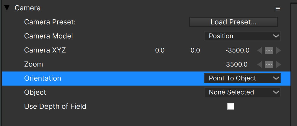
The “Point to Object” Orientation requires you to select an object in the scene, typically an emitter. The “Object” parameter lists every available object, and once selected, the camera always points at that object. The only other thing you can control is the camera position – as with “Point to Target” mode you don’t set any angles.
Even though they’re very similar, you may find “Point to Object” easier to use than “Point to Target”, since the target object is visible in the HUD, and can also be visible in the render (since it may create particles).
Camera Motion Presets
Note that it’s possible to load position path presets into any camera position parameter – more information about the position path presets here.
Camera in Stage View
When the Stage view is set to anything other than “Render View”, the camera position path is displayed:

This makes it easy to see exactly what the camera is doing over time, and also lets you [edit the camera position in the Stage](#widgets) just like emitters or any other object.
Orbit Camera Model
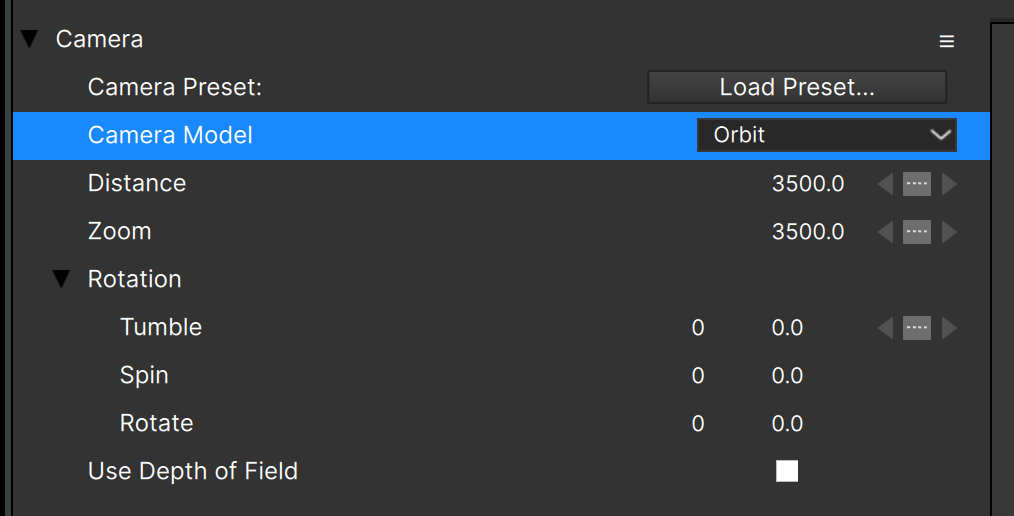
The Orbit camera model is an easy way to move the camera around the origin (0,0,0) while keeping it at the same distance — the camera “orbits” the origin.
Tumble orbits the camera around the world X axis, Spin orbits the camera around the world Z axis, and Rotate orbits the camera around the world Y axis.
Note that “Orbit” camera model is somewhat similar to the Position camera model when using the “Point to Target” orientation, with the Target XYZ set to the origin. The difference is that in the Orbit model the camera is always the same distance away from the origin, unless you change the “distance” parameter of course.
Pan Camera Model
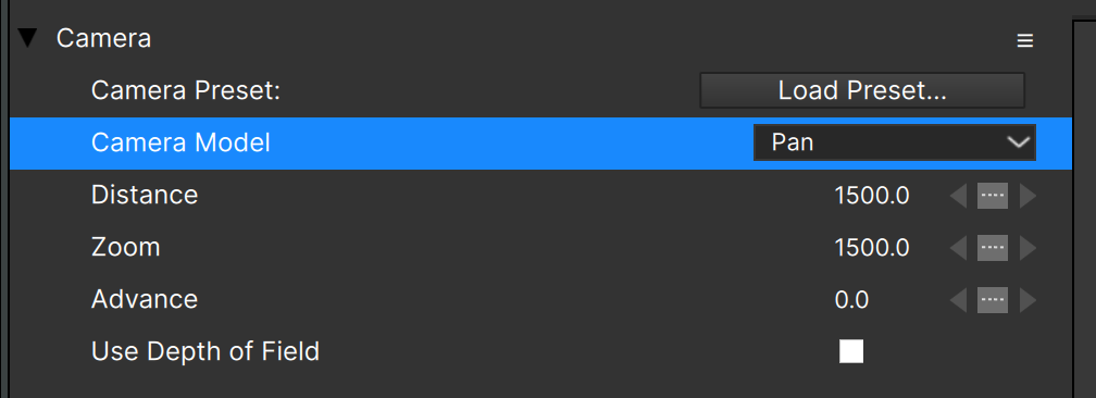
The Pan camera model is a simple way to scroll the scene horizontally. Instead of having position values to set or angles to adjust, there is a single “Advance” parameter that controls the horizontal movement.
Note that the Pan camera model is equivalent to the Position camera model with “Free Rotation” orientation if you have the camera unrotated (Tumble, Spin, and Rotate all 0.0) and adjust only the Position X value.
Depth of Field
Each of the camera models includes a “Use Depth of Field” option that when enabled will blur particles based on their distance from the camera.
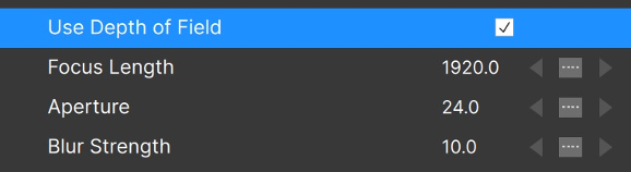
“Focus Length” indicates the distance at which particles will be in focus, and then particles closer or farther away will be blurred.
In many (most?) cases you’ll want “Focus Length” to match the camera “Distance” value.
Aperture and Blur Strength work together to set the maximum blur amount, where larger values will result in more blurring, but also take longer to calculate.
Camera Presets
Unlike general position path presets which can be applied to camera position parameters, camera presets contain values and animation for all camera parameters: zoom, distance, DOF, etc. Particle Illusion ships with a good selection of static and animated camera presets, with and without DOF, and is the easiest way to add a level of sophistication to your particle projects.
There are two different ways to load a camera preset. The first is to click the “Load Preset…” parameter button, which opens the camera preset browser:
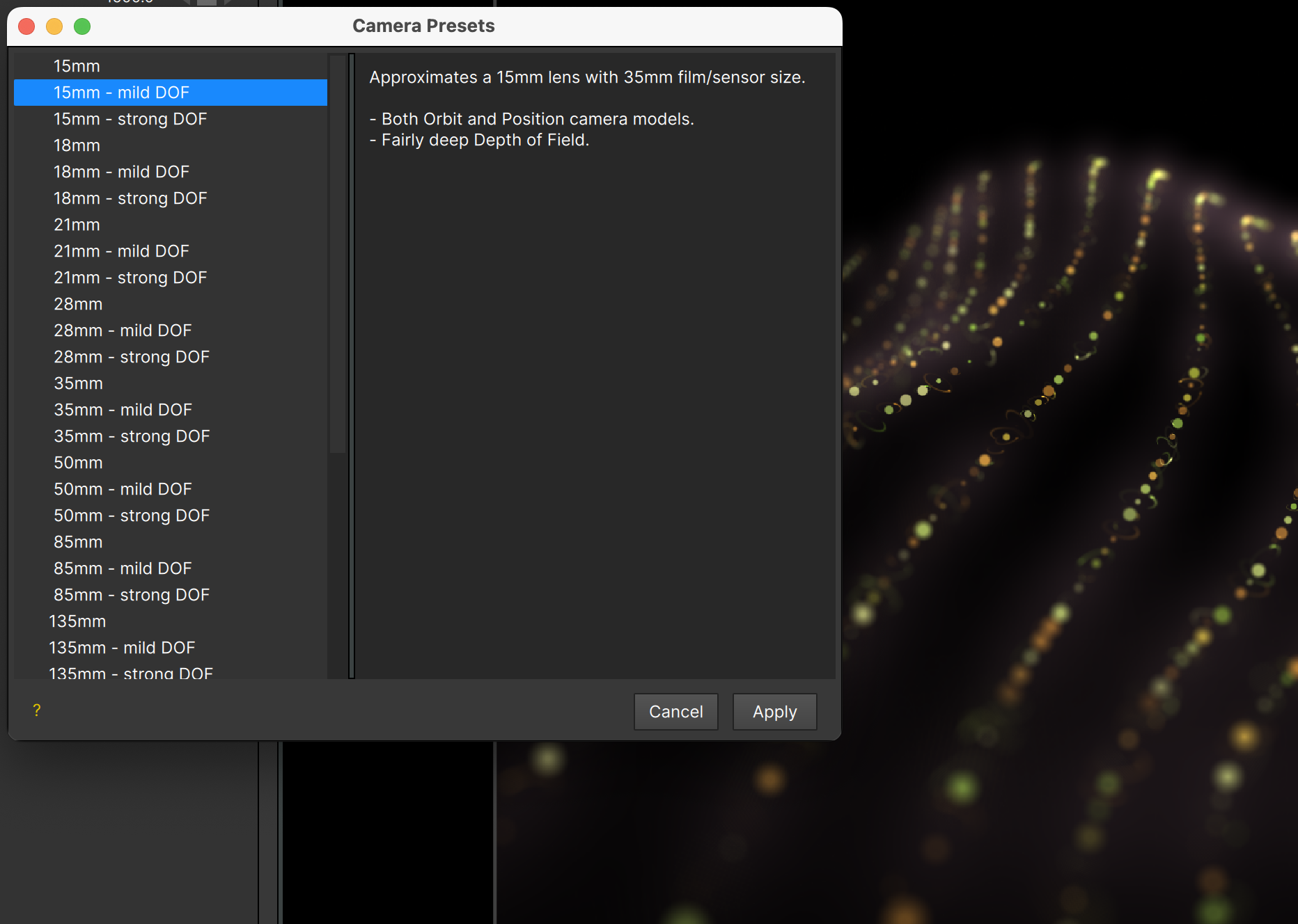
As you select presets in the left view, a description shows in the right, but more importantly the camera is applied so you can see what it looks like in your project.
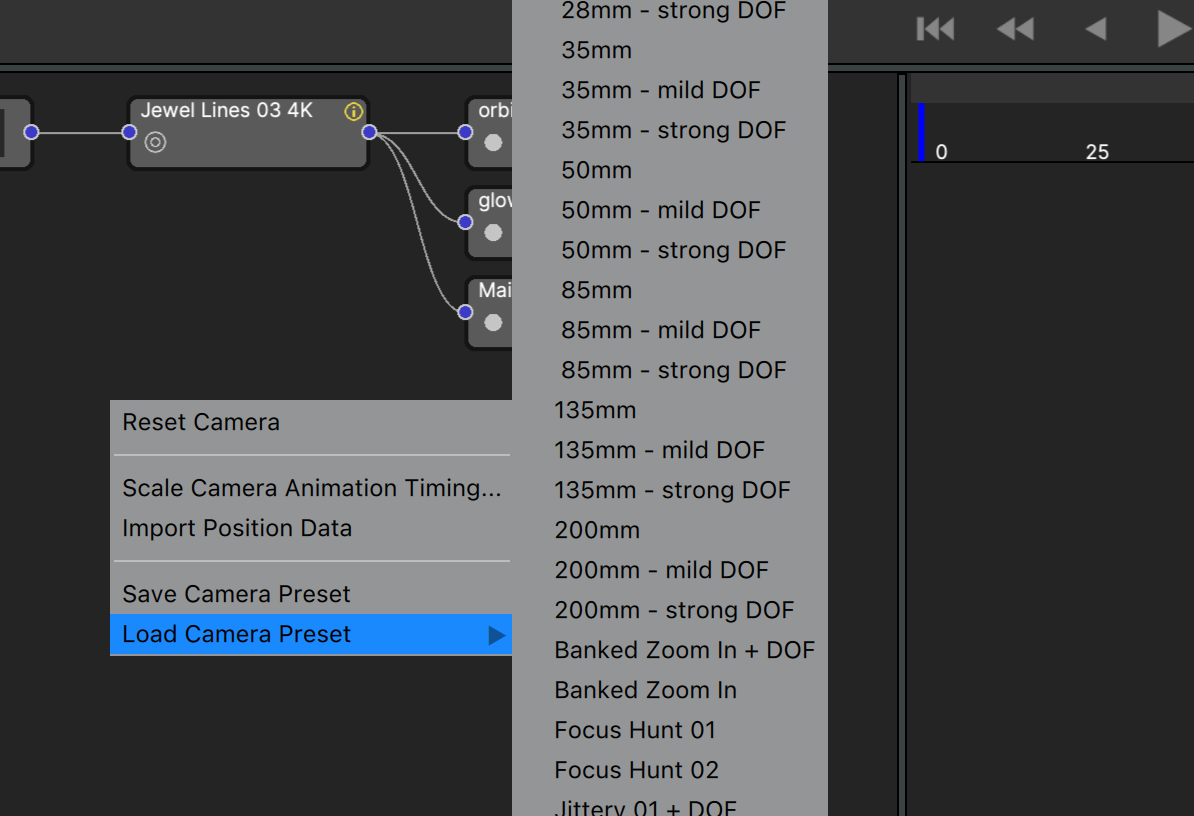
The other, quicker way to select a known, specific camera preset is to use the “load camera preset” menu in the camera hamburger/context menu:
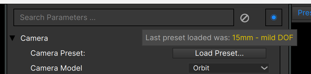
Regardless of the way you load a camera preset, hovering over the “Load Preset…” parameter button will show the name of the last preset you loaded:
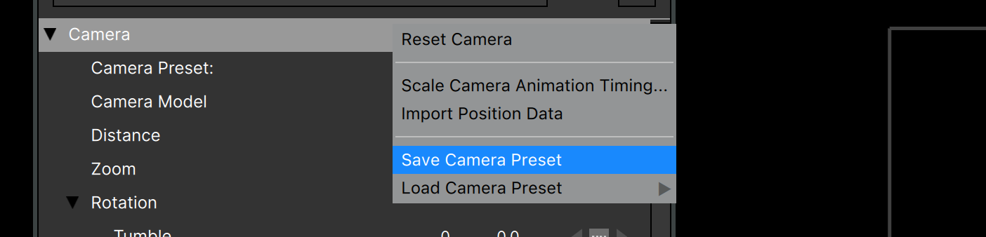
To save a camera preset, use the hamburger/context menu:
Then enter a name and description for the preset:
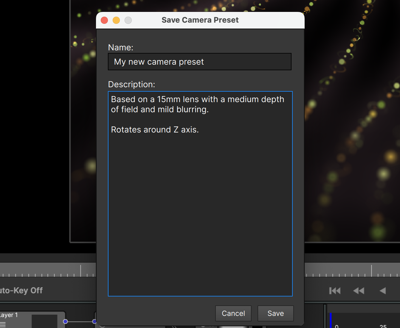
(Note that you can’t edit the description or rename the preset after saving)
As with color gradient, position path, over life graph presets, presets that you save (custom presets) will be designated with a gold dot:
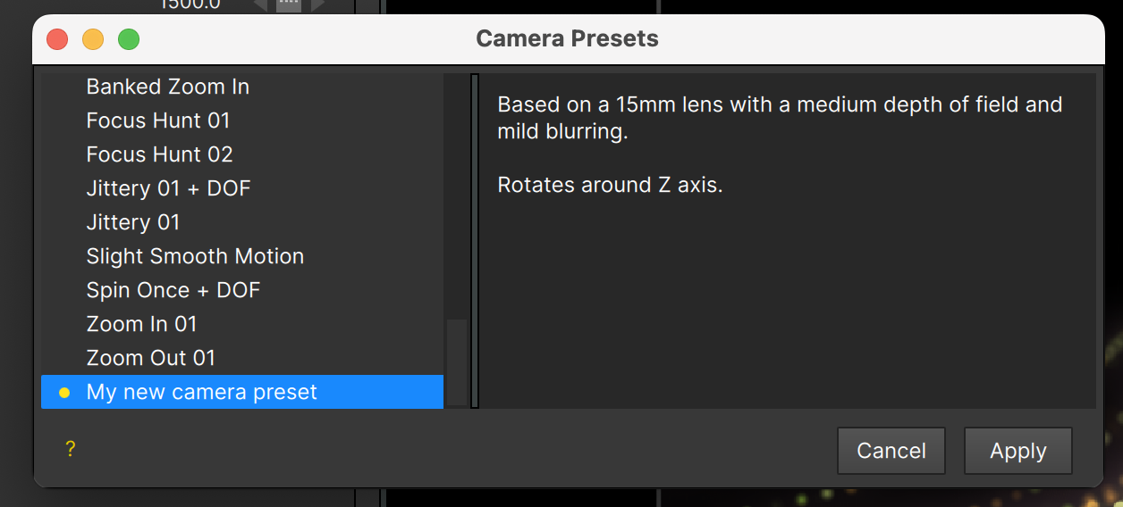
Note that the custom presets are all shown at the end of the list.
(If you want to delete a camera preset, you’ll have to delete the file directly – see the section on File Locations below)
2D vs. 3D Projects
Now that 3D is available, why would you ever want to use Particle Illusion in 2D mode?
Although a large number of emitters work great when converted to 3D, the legacy ones were all created in 2D, and may rely on tricks of the 2D rendering pipeline that no longer exist in the 3D renderer. For instance:
- Emitters that are made primarily of “single” particles to create flat effects, such as HUD or display elements.
- Emitters that rely on particles being drawn in specific order. In 3D mode the particles are sorted by distance from the camera, so the “keep in order” settings (oldest in back, oldest in front) can’t be maintained.
- Super Emitters with particles that use the “preserve color” option for “intense” particles. This relies on particles being drawn for each free emitter in turn, and that’s not possible in 3D mode.
- Any particles that require the “preserve color” option for “intense” particles. “Preserve Color” does nothing in 3D mode, so particles may look a lot brighter and “blown out”.
Also, we didn’t want to force anybody to use 3D if they weren’t comfortable working with it.
So it’s still possible to use Particle Illusion in “2D” mode, although 3D mode is recommended. Therefore when you switch a project to 2D mode, two things will happen: First, you will see a warning message:
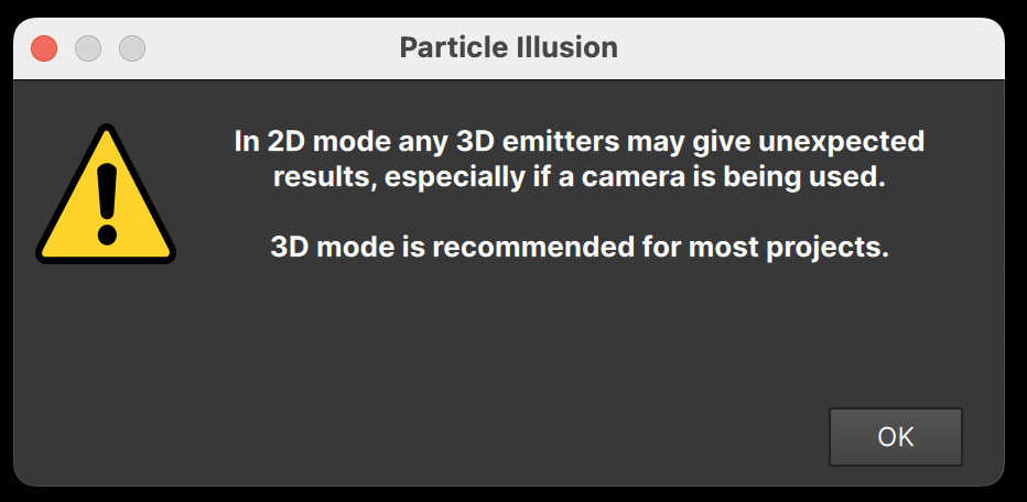
This is just a reminder that some emitters might not work correctly in 2D mode.
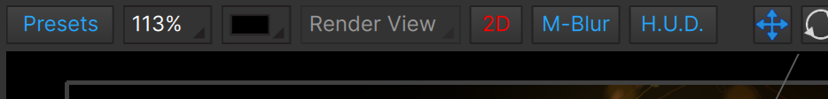
The second indicator that 2D mode is not recommended is that the “2D” button above the stage will show in red:
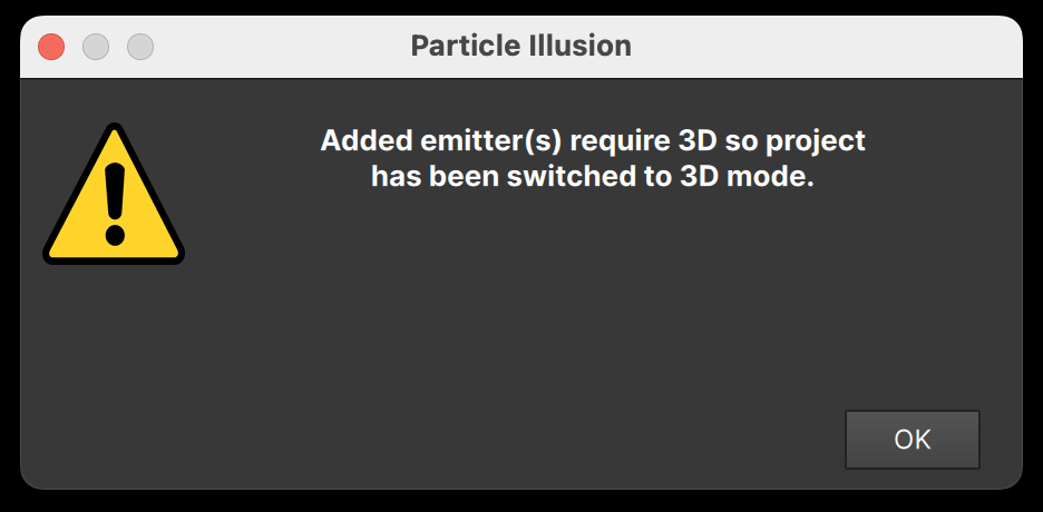
Finally, note that if the project is in 2D mode but you add an emitter that requires 3D - for instance an emitter that uses a 3D model - the project will automatically be switched to 3D and you’ll be notified:
Emitter Properties
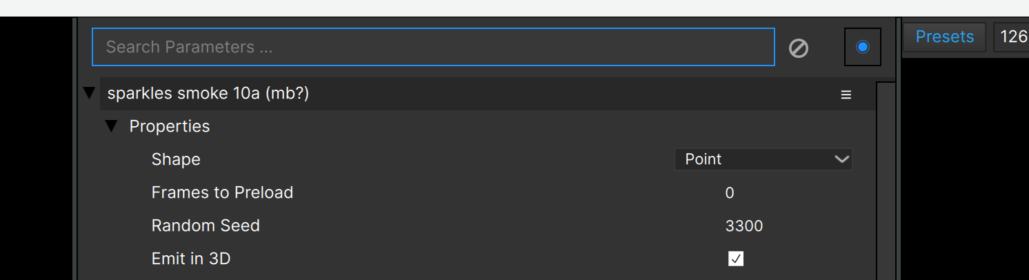
Going back to the “Properties” group now, you’ll see controls for preload, emitter shape, and more:
“Shape” describes the shape of the emitter from which particles are created, and allows you to switch between “Point”, “Line”, “Area” (rectangle), “Ellipse”, and “Circle” in 2D projects. In 3D, “Area” is replaced by “Plane”, and “Box” and “Sphere” shapes become available, as well as “3D Model”.
Note that additional parameters will be visible for some of these shapes, and will be covered in more detail later.
(Emitter Shape is different from the particle “shape” — also called “sprite” — which is the image used for each particle.)
“Frames to Preload” sets the number of frames that the emitter will run before its first frame in the project, allowing it to have many particles visible at the start instead of starting from zero particles. Library emitters that take a while for their effects to evolve will usually have “Frames to Preload” set to a non-zero value.
“Particle Order” determines if the particles will be drawn in order: oldest first, oldest last, or unordered. Unless the specific effect requires particles to be drawn in order, it’s best to set this to “Unordered”. Some types of effects that might require particles to be drawn in order are heavy smoke trails, geometric effects, and effects that are animated to grow/shrink over time (as if the emitter were coming toward or moving away from you). Note that particles flagged as “intense” always combine in a way that makes “in order” drawing inapplicable. (“Intense” particles will be covered in the “particle type” section below). Note that this setting does not have an effect in a 3D project.
“Random Seed” is the value used to generate the random numbers used in generation of particles, adding variation, and more. Changing this value by any amount will result in a different pattern of particles, and is the easiest way to get a new version of the effect.
“Emit in 3D” is only available when the project is 3D, and should be checked to get particles in 3D space. When NOT checked in a 3D project, the particles will all be created on a plane, which can be very obvious if the camera moves. Note that when a project is 3D, any emitters added will automatically have this option checked, but you can uncheck it manually.
“3D Lines” (added in 2024.0) relates to the drawing of particle lines (covered later). With this unchecked, those lines are drawn as 2D elements. Turn this on if you have lines that need to show more perspective or depth – especially effective if particles are moving close to the camera.
In this example the red particles are using 2D lines, and the blue are using 3D:
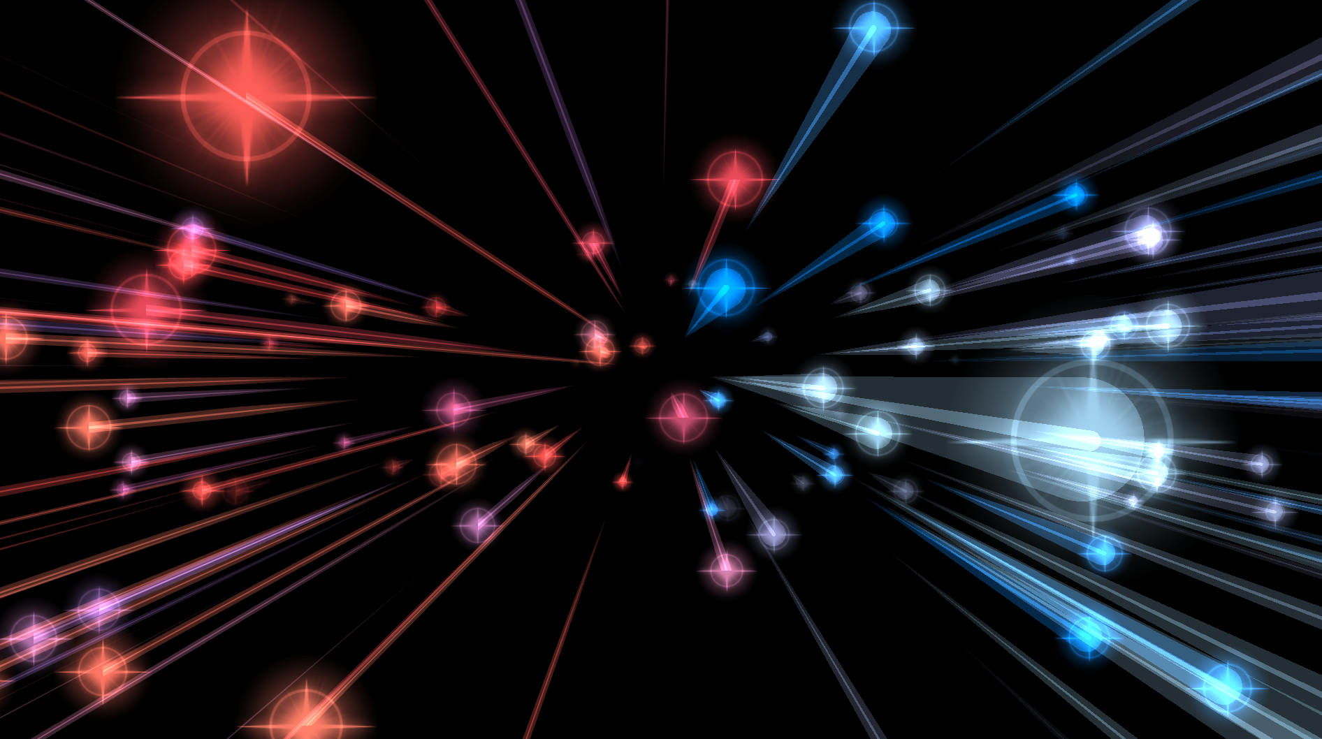
Notice that all of the red lines are the same width, regardless of how close to the camera the particles pass, while the blue particles show much more depth and perspective.
You may find that 3D lines draw a bit more slowly than 2D lines, or that they have a less-refined look. Plus some presets made with 2D lines may not look correct with 3D lines.
Note that this is an emitter-level setting, so you can’t mix 2D and 3D lines in the same emitter.
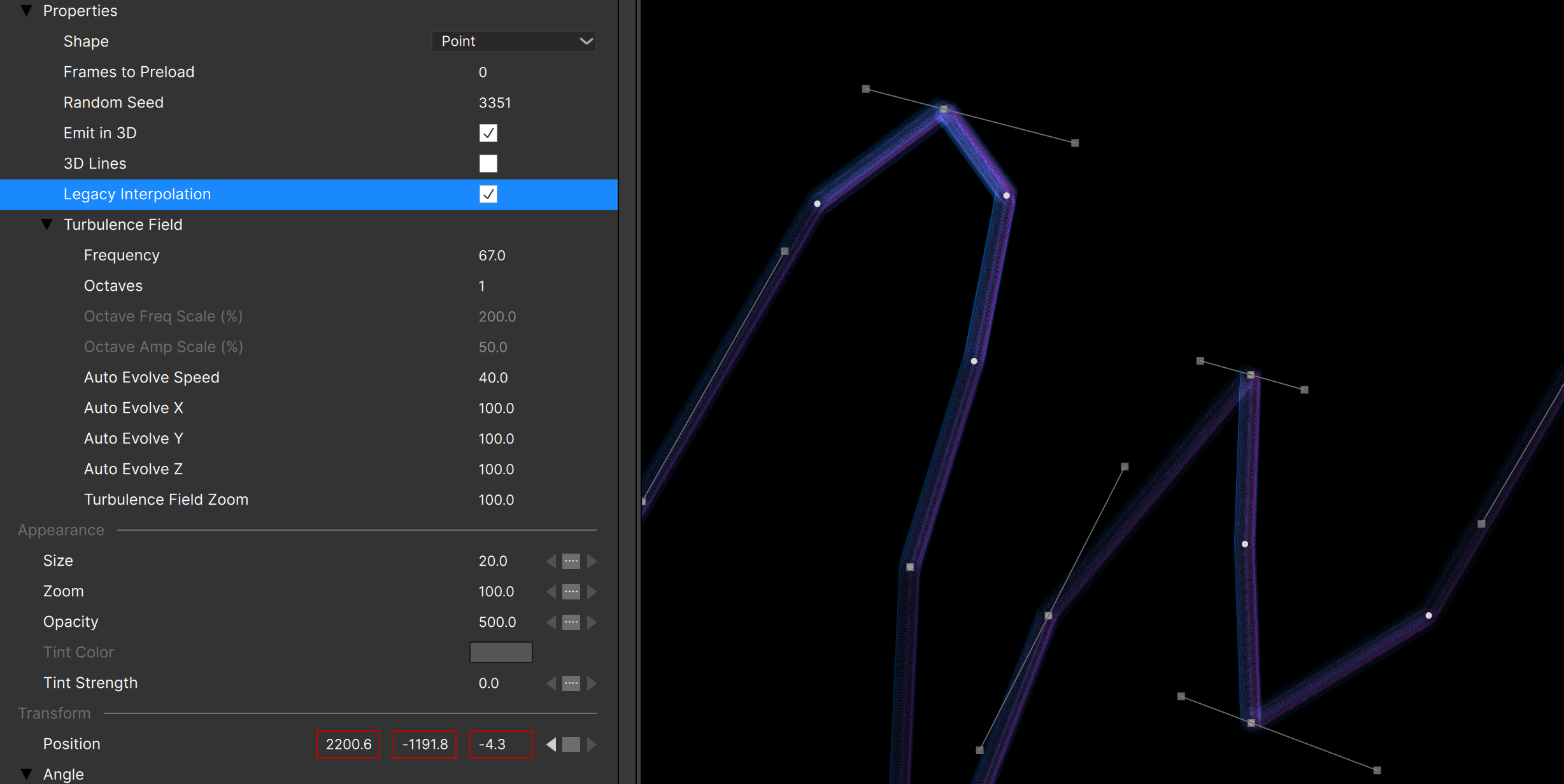
Legacy Interpolation
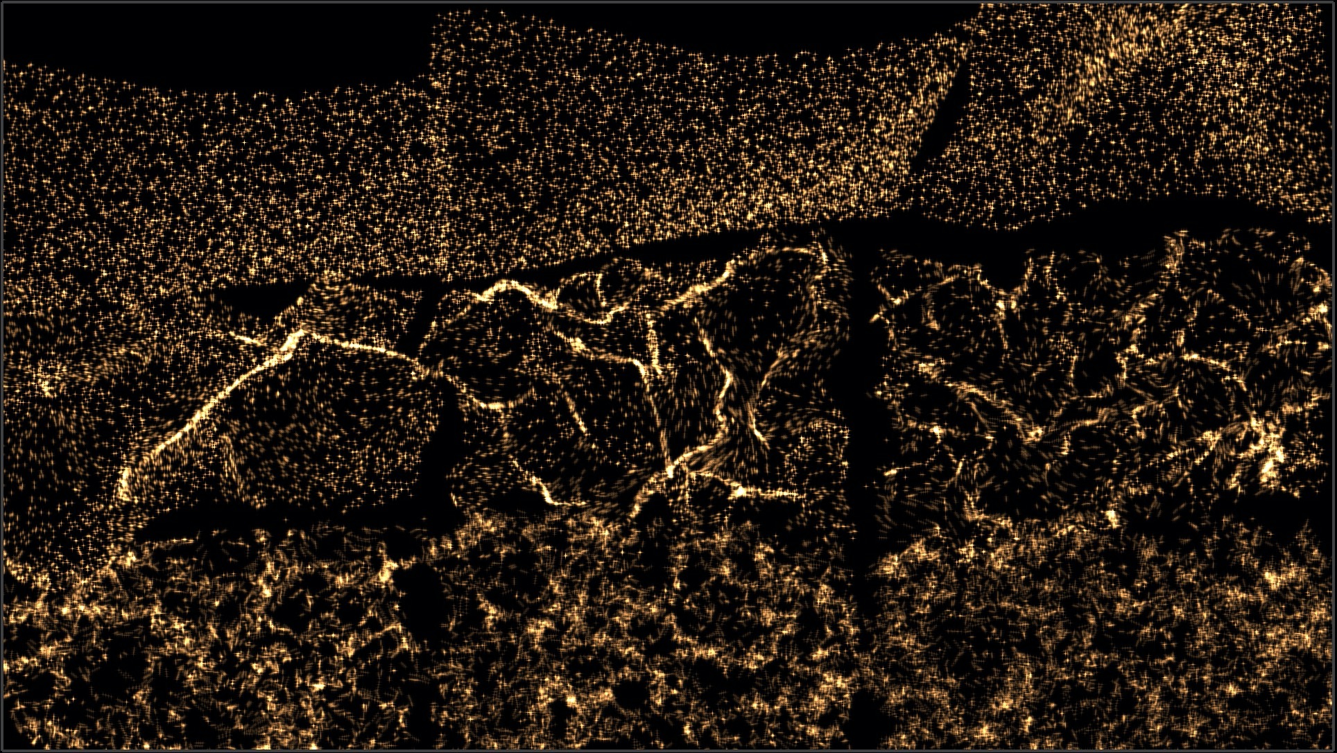
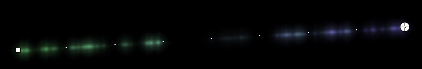
The “Legacy Interpolation” parameter is new in 2026.0, and it relates to the positions of particles when they are created by a moving emitter. In 2025.5 and earlier versions all particles were added on a straight line connecting the emitter position at each frame. In most cases this produces perfectly fine results – you may not have ever noticed this was happening.
For fast-moving emitters though this could be a big problem, especially if the particles were stationary, as is the case with any “writing” style emitters.
Particles can now be added at precise locations that follow the emitter location exactly, or at straight-line positions if you prefer – the “Legacy Interpolation” determines which method is used.
With “Legacy Interpolation” checked, you get the classic behavior:
As you can see the emitter is moving quite quickly, and the particles end up creating a very sharp, “low resolution” pattern.
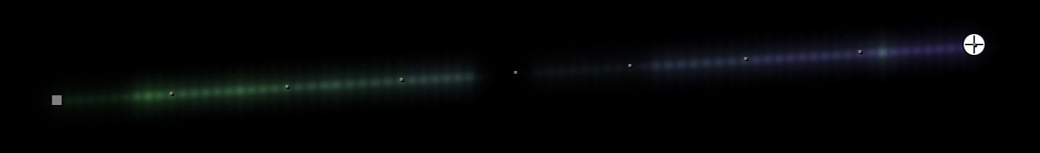
With “Legacy Interpolation” unchecked, you get the new, improved behavior:
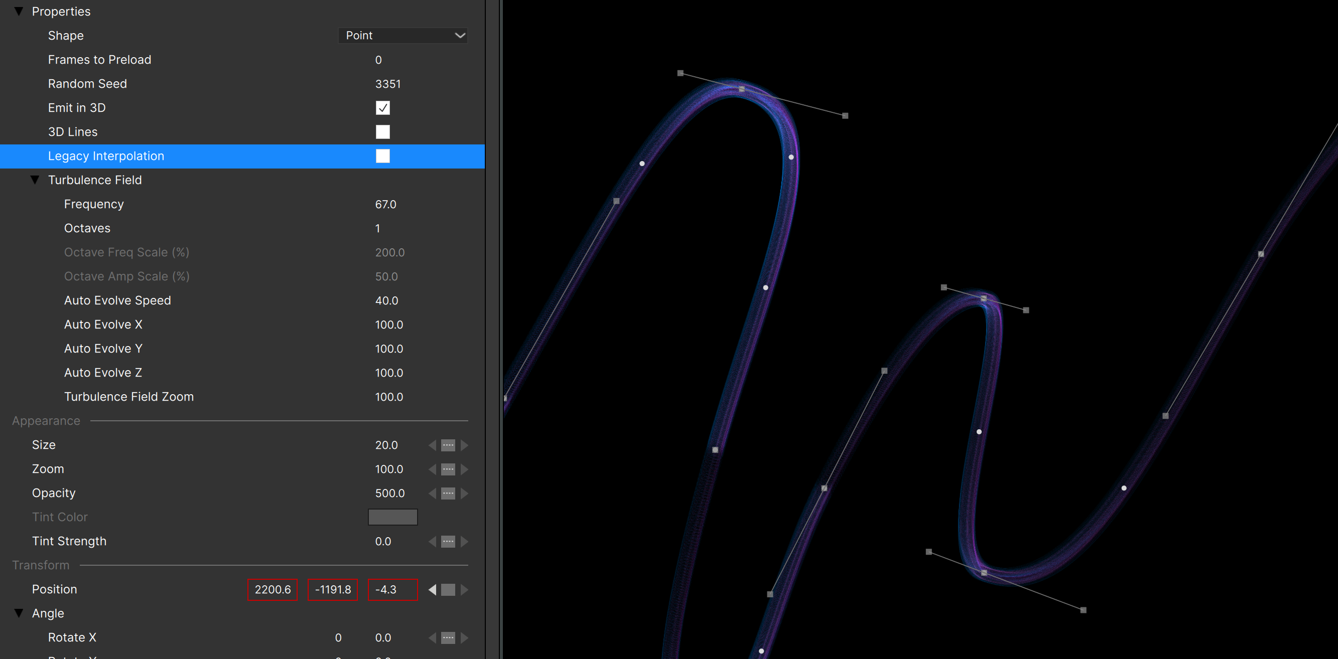
Obviously this is much smoother and more visually appealing!
Note: Any new emitters you add to any project (old or new) will have “Legacy Interpolation” unchecked so you get the improved behavior. Emitters in projects that were created with 2025.5 or earlier will have “Legacy Interpolation” checked so that they do not change appearance.
Legacy Alignment
The “Legacy Alignment” parameter is new in 2026.5, and is useful if you notice that particle positions have changed in older presets or projects. If you notice that your particles are moving strangely with a rotating emitter, uncheck this parameter. (A long-standing issue related to emitter rotation was fixed in 2026.5, but if you need the previous behavior, check this parameter.)
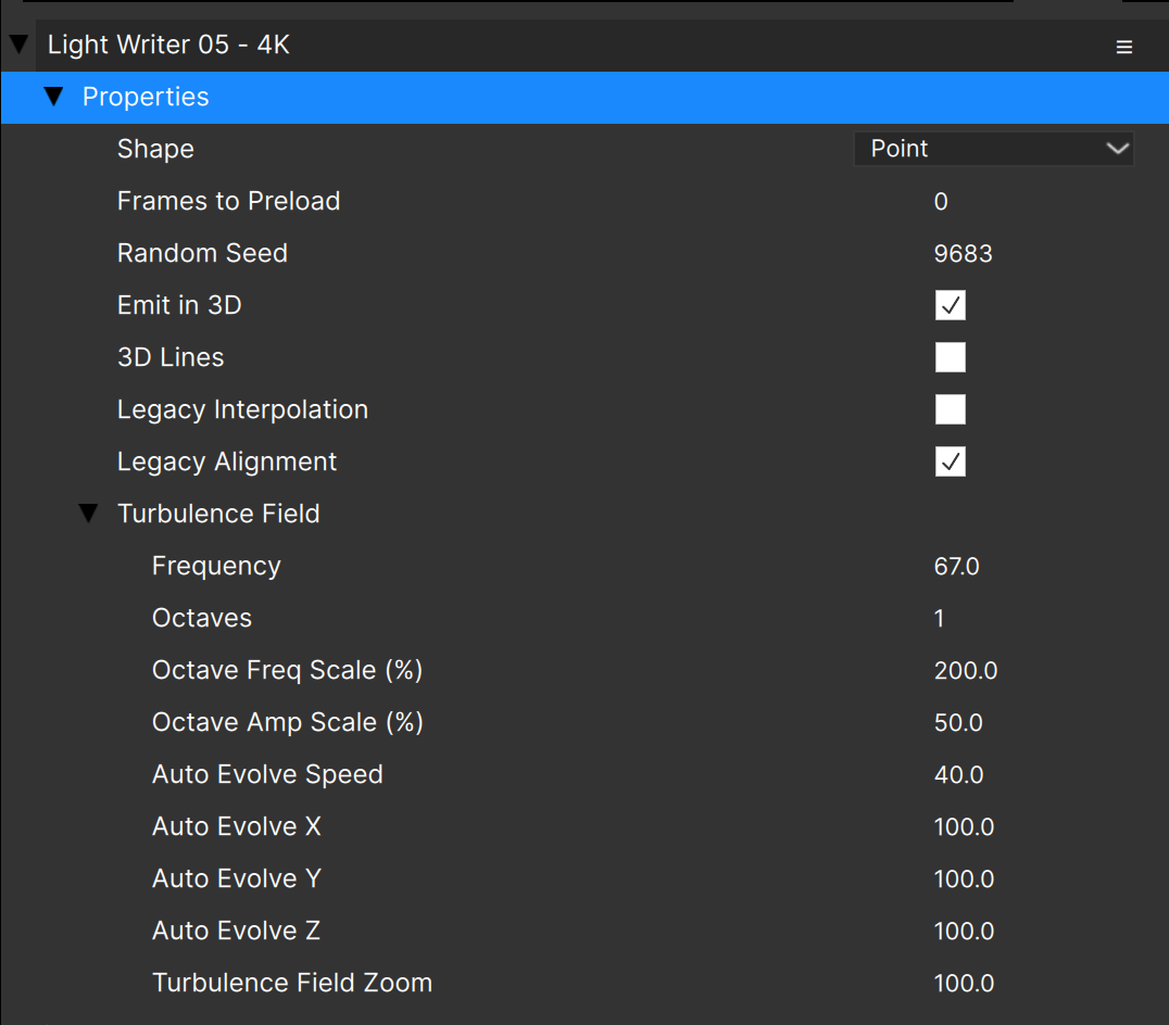
Turbulence Field
The “Turbulence Field” group of parameters controls the noise pattern used to displace particles and free emitters in space and/or change their size. This 3D turbulence field is created by one or more “octaves” of noise that are added together.
Note that these parameters only have an effect if the Position Turbulence and Size Turbulence values are non-zero.
“Frequency” is the base frequency of the first noise pattern. In general it sets the “size” of the noise pattern, with higher values resulting in a smaller overall pattern.
“Octaves” is the number of noise total patterns that are added, with each copy having a frequency and amplitude determined by the next two parameters.
“Octave Freq Scale” is the multiplier used to determine the frequency of the octave. A value of “200” means that each octave added will have double the frequency of the previous. A value of “100” makes the number of octaves have no visible result. Note that with an “Octaves” value of “1” this parameter has no effect.
“Octave Amp Scale” is the multiplier used to determine the amplitude of the octave. A value of “50” means that each octave added will be half the amplitude (strength) of the previous. Note that with an “Octaves” value of “1” this parameter has no effect.
Using the default values of 200% for Octave Freq Scale and 50% for Octave Amp Scale, adding octaves has the visual effect of adding “detail” to the turbulence field.
Note that 2 or 3 Octaves is usually sufficient for adding detail, and that the higher the number of octaves, the slower the calculation (although the slowdown may not be noticeable).
“Auto Evolve Speed” is used to animate the turbulence field. This is useful for particles that are not moving, or to create a kind of “waving” effect. The higher the value, the faster the noise field will animate.
“Auto Evolve X/Y/Z” can be used to scale the turbulence field animation along each axis. For instance if you don’t want it to evolve along X, you can set “Auto Evolve X” to 0.
“Turbulence Field Zoom” allows you to scale the entire field, as if you were zooming in to or away from it and provides an alternate way to control the apparent frequency of the noise pattern.
Particle Parameters
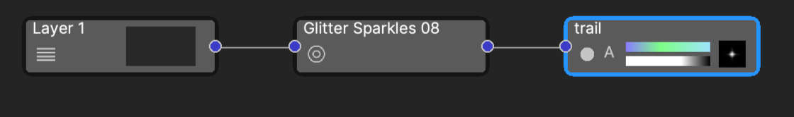
Remember that many of the parameters of the emitter are scaling factors that are applied to its child particle types (and free emitter types it has). In this example, the emitter is a regular (non-super) emitter with a single particle type named “trail”:
With the particle type node selected, the Controls View looks like this:
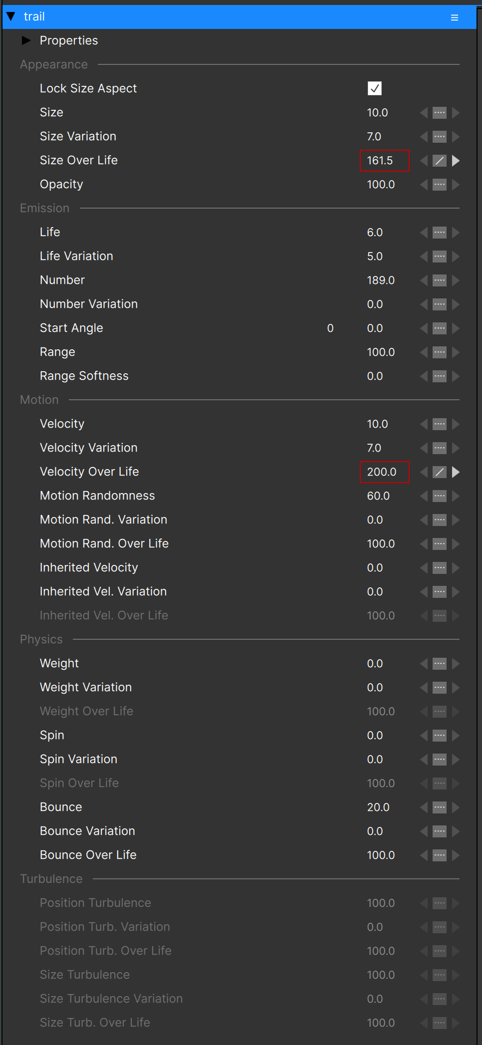
It has many of the same parameters as seen previously with the emitter selected, with some differences. (As before we’ll skip the “Properties” group initially)
“Lock Size Aspect”: When unchecked shows separate Size X and Size Y parameters (also Variation and Over Life) to allow you to stretch particles.
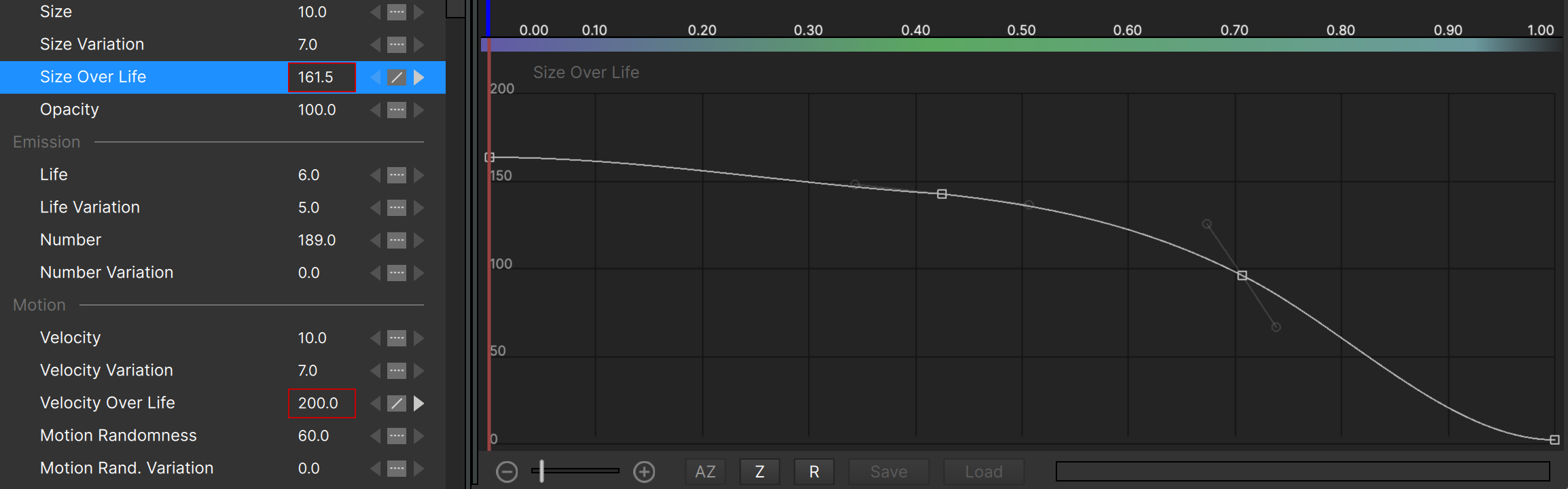
“Size”: The size of the particles. An arbitrary value with no physical meaning – a value of “10” does not mean “10 pixels”. All you can say is that a value of “10” creates particles twice as big as those with a value of “5”.
“Size Variation”: The range of values around the base “Size”. Values can vary from the base value by +/- half this value. (In the image above the “Size” is 10.0 and the “Size Variation” is 7.0, which means that particles will be created with a size that is anywhere from 6.5 to 13.5.)
“Size Over Life”: How the particle’s size changes over the life of the particle. See the section on “over life” parameters below.
“Opacity”: The opacity (visiblity) of all particles of this type. Does not affect particle lines that have “Line Opacity Type” set to “Specify”
“Life”: How long particles are alive. An arbitrary value with no physical meaning – this is not number of frames or seconds. All you can say is that particles with a value of “10” live twice as long as those with a value of “5”.
“Life Variation”: The range of values around the base “Life”. Values can vary from the base value by +/- half this value. (In the image above “Life” is 6.0 and “Life Variation” is 5.0, which means particles will be created with a life that is anywhere from 3.5 to 8.5.)
“Number”: A relative value determining how many particles are created. An arbitrary value with no physical meaning – it does mean particles per second or per frame. All you can say is that a value of “10” means that twice as many particles will be created in the same amount of time for a value of “5”.
“Number Variation”: Variation in the rate of particle creation. It’s a bit difficult to see the effect until the value gets higher, and then you’ll see fewer particles created at times, and more at other times.
“Start Angle/Offset”: (not for Point or 3D Model) When Range is not 100 this sets where on the shape the range falls.
“Range”: (not for Point or 3D Model) The percentage of the shape that creates particles of this type. Depends on the specific shape.
“Range Softness”: (not for Point or 3D Model) The falloff or softness for the ends of the particle range.
“Wrap Offset”: (not for Point or 3D Model) For shapes that have Start Offset (not Start Angle) this determines if values higher than 100 wrap back around.
“Velocity”: The particle’s rate of motion along a straight line. An arbitrary value with no physical meaning – it’s not pixels per second or anything like that. All you can say is that a value of “10” means that the particles move twice as fast as with a value of “5”. (Probably should have been named “Speed” since it’s a scalar and not a vector)
“Velocity Variation”: The range of values around the base “Velocity”. Values can vary from the base value by +/- half this value. (In the image above “Velocity” is 10.0 and “Velocity Variation” is 7.0, which means particles will be created with a life that is anywhere from 6.5 to 13.5.)
“Velocity Over Life”: How the particle’s velocity changes over the life of the particle. See the section on “over life” parameters below. Note that due to a quirk in the PI engine, “Velocity Over Life” will also affect a particle’s weight.
“Motion Randomness”: Adds a “wandering” type of motion to particles, completely independent of the motion from “Velocity”.
“Motion Rand. Variation”: The range of values around the base “Motion Randomness”. Values can vary from the base value by +/- half this value.
“Motion Rand. Over Life”: How the particle’s motion randomness changes over the life of the particle. See the section on “over life” parameters below.
“Inherited Velocity”: The amount of motion a particle gets from its parent emitter as it moves. If the parent emitter isn’t moving, this will have no effect. An arbitrary value with no physical meaning – a value of “10” means that the particles have twice as much inherited velocity as with a value of “5”.
“Inherited Velocity Variation”: The range of values around the base “Inherited Velocity”. Values can vary from the base “Inherited Velocity” value by +/- half this value.
“Inherited Velocity Over Life”: How the particle’s inherited velocity changes over the life of the particle. See the section on “over life” parameters below.
“Weight”: Determines if particles rise or fall (gravity). This value can be positive or negative. When the value is positive, particles will fall – negative weight makes particles rise.
“Weight Variation”: The range of values around the base “Weight”. Values can vary from the base value by +/- half this value. Note that if “Weight Variation” is large enough it’s possible to have some particles fall and others rise (since weight can be positive or negative).
“Weight Over Life”: How the particle’s weight changes over the life of the particle. See the section on “over life” parameters below.
“Spin”: How much, and in which direction, a particle spins around its reference point. This value can be positive or negative. Positive spin values results in clockwise rotation, negative is counterclockwise (anticlockwise).
“Spin Variation”: The range of values around the base “Spin”. Values can vary from the base value by +/- half this value. Note that if “Spin Variation” is large enough it’s possible to have some particles rotating in both directions (since spin can be positive or negative).
“Spin Over Life”: How the particle’s spin changes over the life of the particle. See the section on “over life” parameters below.
“Bounce”: How much a particle bounces when it hits a deflector object. Note that a value of “0” does NOT mean that particles will stick to deflectors.
“Bounce Variation”: The range of values around the base “Bounce”. Values can vary from the base value by +/- half this value.
“Bounce Over Life”: How the particle’s bounce changes over the life of the particle. See the section on “over life” parameters below.
“Position Turbulence”: The amount the particle’s position is offset by the turbulence noise function (see above section). Note that a particle does not need to be moving for this to apply.
“Position Turb. Variation”: The range of values around the base “Position Turbulence”. Values can vary from the base value by +/- half this value.
“Position Turb. Over Life”: How the particle’s position turbulence changes over the life of the particle. See the section on “over life” parameters below.
“Size Turbulence”: The amount the particle’s size is affected by the turbulence noise function (see above section).
“Size Turbulence Variation”: The range of values around the base “Size Turbulence”. Values can vary from the base value by +/- half this value.
“Size Turb. Over Life”: How the particle’s size turbulence changes over the life of the particle. See the section on “over life” parameters below.
Normal Parameters vs. “Over Life” Parameters
The normal parameters like “Size” and “Velocity” designate the values that will be used at birth - at the instant the particle is created. Even if these parameters are animated (change over time) this is still true. So if the “Velocity” parameter for instance starts at 0 for several frames before increasing, the particles created when velocity was 0 will not move even when the velocity value has increased.
Said another way: when a particle is created, it uses the parameter values from that instant – any changes to those parameters at other times will not affect this particle.
To change any parameter for particles over time, use the “Over Life” version of the parameter.
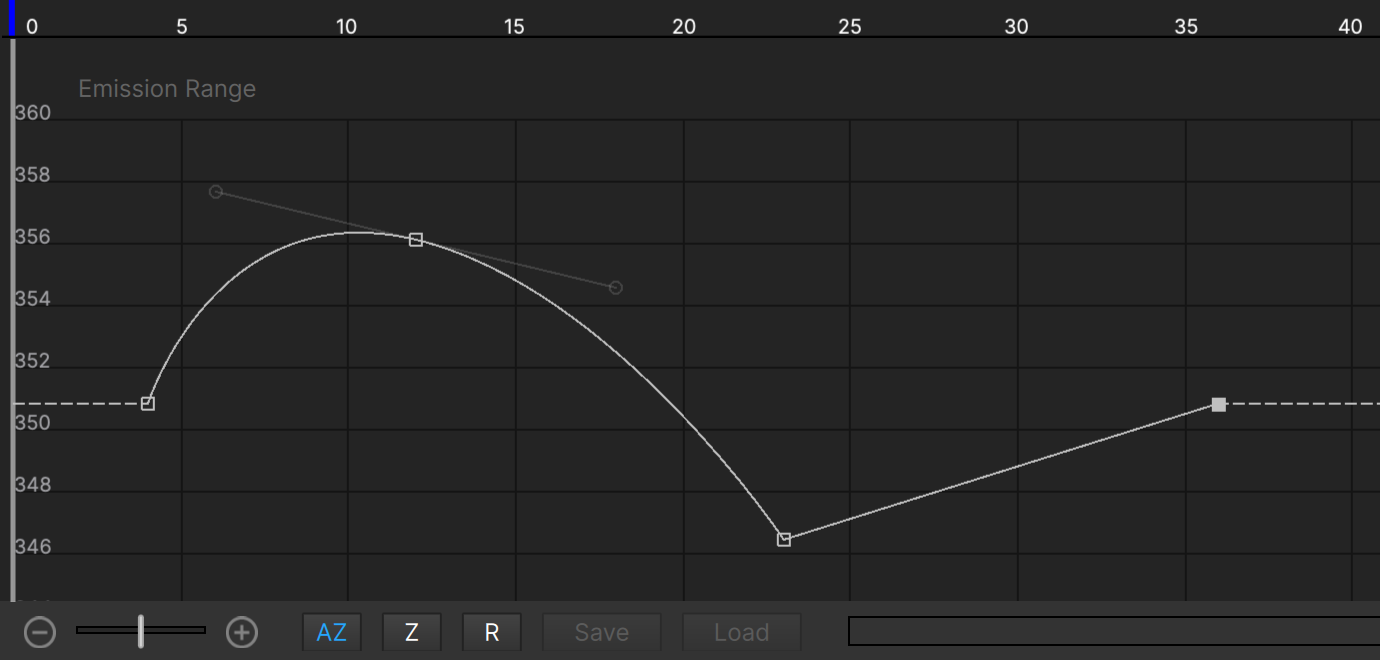
For instance to change the particle velocity over time you use the “Velocity Over Life” parameter. When this or any “Over Life” parameter is selected, the Graph View changes:
(To see the entire over life graph you may need to hit the “R” button to reset the graph range.)
For “Over Life” parameters the horizontal scale of the Graph View no longer shows frame numbers, but instead displays the percentage of the particle’s life. On the left is 0.0, the birth of the particle, and on the far right 1.0, the particle’s death. In the example above for “Size Over Life” you can see that the particle starts large, slowly decreases in size until about 70% (0.7) of its life has passed, then more quickly decreases until it ends its life with a size of 0.
Note that this is independent of how long the particle actually lives; whether it is alive for 10 frames or 500 its size will follow this graph over its life.
De-Emphasized Parameters
You may have noticed that some parameters are darkened for some emitters, free emitters, particle types, etc. These parameters are not disabled, but are “de-emphasized” because they have no effect.
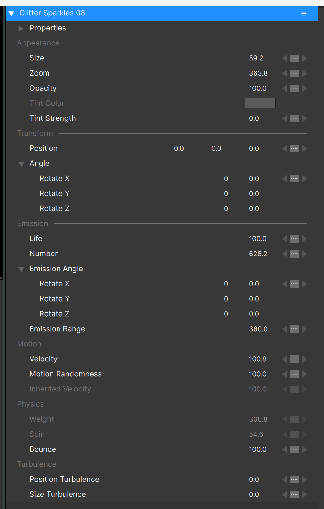
Let’s take the following example of the “Glitter Sparkles 08” emitter (found in the “Sampler” library). With the emitter node selected you can see that both “Weight” and “Spin” are de-emphasized:
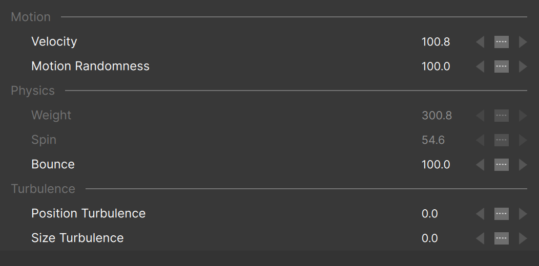
Parameters are de-emphasized when a related parameter causes then to have no effect. To see what this means, let’s look at the particle parameters for this same emitter:
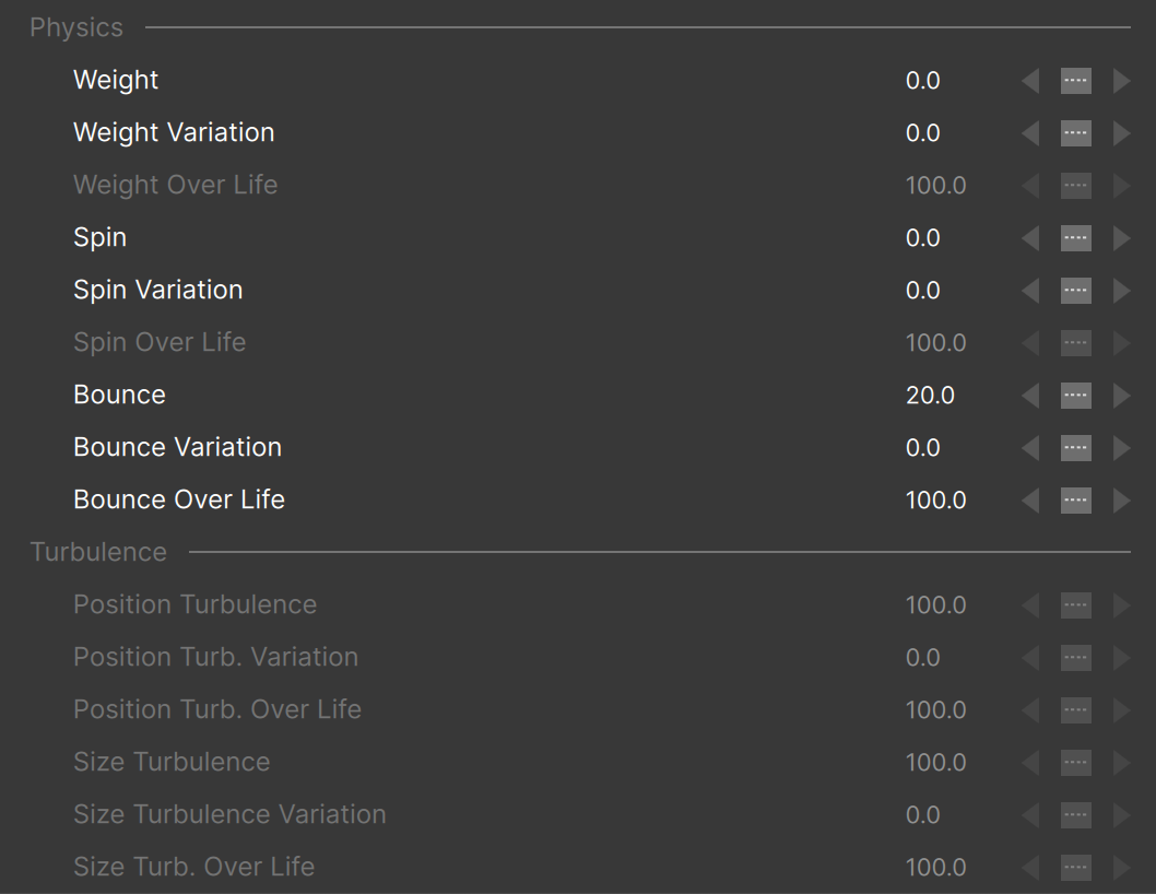
First let’s look at “Weight”. You can see that both “Weight” and “Weight Variation” are 0.0. Since this emitter (Glitter Sparkles 08) only has a single particle type, and since the emitter parameters are scaling factors, it doesn’t matter what the emitter “Weight” value is – it will have no effect on the particles. Scale “0.0” by anything and you still get “0.0”, so the emitter “Weight” parameter is de-emphasized.
Similarly the “Spin” parameter is de-emphasized at the emitter level because the particles have no spin.
Note also that the “Weight over life” and “Spin over life” parameters are de-emphasized, again to remind you that they have no effect.
It’s important to note that although parameter de-emphasis will usually make it easier to focus on the parameters that matter, there is one case where it can cause some confusion: animated parameters.
Take this example:

This is a common graph of an emitter “Number” parameter for an explosion or other type of burst; the “Number” is some non-zero value for a few frames and then steps down to 0 to “turn off” the creation of particles.
If you then look at the particle node “Number” parameter, if the current time indicator (CTI) is between frames 0 and 5, the particle “Number” parameter will not be de-emphasized. If the CTI moves past frame 5 though, the parameter will be de-emphasized since the emitter “Number” is now 0:
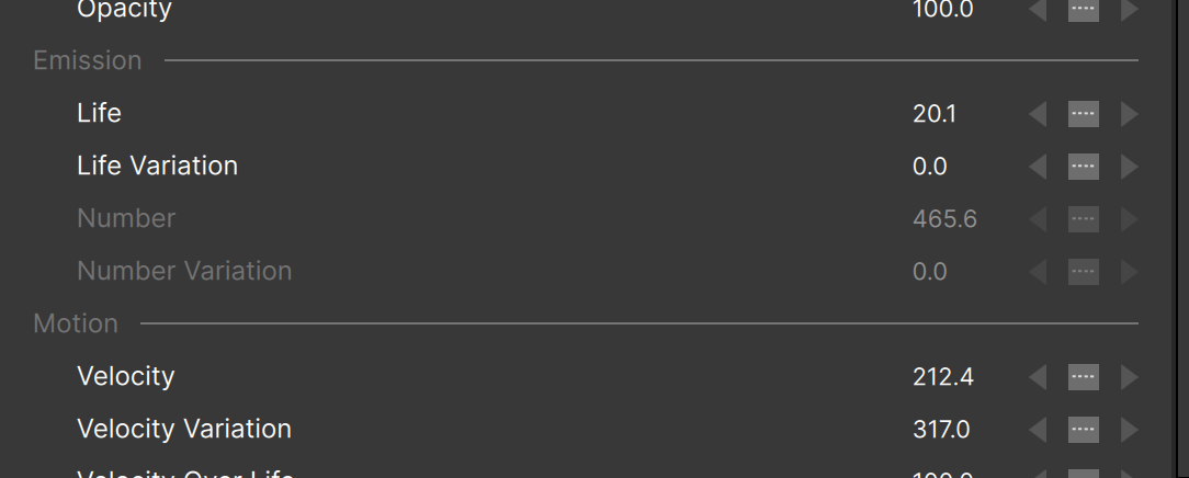
If you change the particle “Number” parameter (or “Number Variation”) you will still see the number of particles change even though this parameter is de-emphasized.
Emphasized Parameters
Parameters are de-emphasized automatically to show when they have no effect. At times you may want to highlight or “emphasize” certain parameters because they are important to the effect, changing them will produce interesting variations, or you just want to bring attention to them for some reason.
For example, the “Size Over Life” parameter here:
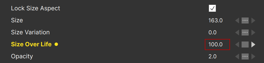
Emphasized parameters are drawn with bold, golden yellow text, and are followed by a golden yellow dot.
To emphasize a parameter, r-click on the parameter name and select “emphasize”. Alternately you can double-click a parameter name to toggle this setting.
Note that this emphasis is for decoration only – it has no bearing on how the parameter or effect behaves.
Graph View
Parameters that are selected in the Controls View have their animation displayed in the Graph View:

Using the graph view you can change the values of data keys, reposition them, delete keys, or create new ones.
To delete a key, select it in the graph window, then press your keyboard’s “delete” key, or ctrl-click (cmd-click on Mac) directly on the key.
To change a key from linear to bezier, alt-click it (option-click on Mac).
You can disconnect bezier handles by alt-clicking on one of them (option-click on Mac).
To add a new key, ctrl-click on the graph (cmd-click on Mac) – but not on an existing key.
Note that it’s possible to select multiple points in the graph (for moving or deletion).
The controls at the bottom of the Graph View allow you to zoom the graph:
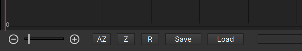
- The slider (and -/+ buttons) control the horizontal zoom level.
- The “AZ” button is “Auto-Zoom”, and will automatically adjust the vertical scale and range of the graph so the data keys fill the graph.
- When “Auto-Zoom” is turned off, the “Z” button will do the same thing manually.
- The “R” button will reset the graph both vertically and horizontally, showing the entire range of values.
- The “Save” and “Load” buttons only apply to “Over Life” and Position parameters, and are used for saving and loading presets.
Over Life Graph Presets
When any “Over Life” parameter is selected, the “Save” and “Load” buttons below the graph view are enabled. Clicking “Load” opens the Preset Dialog:

It’s straightforward: double-click any preset or select and click “Apply”.
The buttons at the bottom allow you to delete any preset, rearrange them by moving the selected one up or down, resize the presets to fit your personal preference, or to restore all factory-installed presets (in case you’ve deleted some).
Presets that you’ve saved yourself – using the “Save” button below the Graph View – will show with a yellow dot:

Note that using the “Restore” button will move all of your custom presets to the top of the preset list.
Position Path Presets
When any “Position” parameter is selected – one that has X/Y/Z coordinates (or X/Y in 2D mode), the “Save” and “Load” buttons below the graph are also enabled. Clicking “Load” opens the Position Path Preset Dialog:

Like the other preset dialogs, the buttons at the bottom allow you to delete any preset, rearrange them by moving the selected one up or down, resize the preset display to fit your personal preference, or to restore all factory-installed presets (in case you’ve deleted some), and presets that you’ve saved yourself – using the “Save” button below the Graph View – will show with a yellow dot.
Unlike the over life graph presets though, these presets contain 3D data. Use the view selector to change viewpoints:
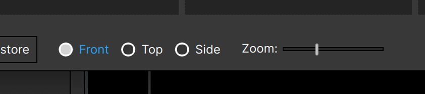
And use the zoom slider to change the preview zoom factor – in case there are points outside the frame area that you need to see.
Note that a preset that looks too simple to be useful in one view may reveal its complexity in another – a circle in front view becomes a spiral in top view for instance, or what looks like a tiny movement in the front view shows that it is a deep Z push in the top view.
Transform Position Path
After applying a position path preset, the Transform Position Path dialog automatically opens:
![]()
This allows you to act on the entire position path at once: scale it, rotate, and/or translate (offset) the path.
The sliders in this dialog have limited range, but you can click on the value and enter any value you need.
Note that you can only scale and rotate, or scale and translate – if you want to do all three just use the transform feature twice. You can activate the Transform feature any time a Position parameter that contains animation is selected by either R-clicking on the Position parameter in the Controls View:
![]()
or by selecting the Position parameter and using the Action menu:
![]()
Remember that it’s possible to translate (reposition) the entire path in the Stage by Ctrl-dragging (Cmd-dragging on Mac) the emitter, but the Transform Position Path feature is more precise.
Scale Animation Timing
So you’ve applied a position path preset, and maybe scaled it down or rotated it – but it’s moving much too slowly (or quickly) along the path. How do you fix that?
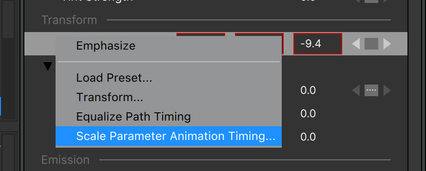
If you only want to scale the animation of the position parameter (or any other single parameter that contains animation) R-click on the parameter in the controls view and select “Scale Parameter Animation Timing…”
The Scale Animation Timing dialog opens, where you can set the scale factor for the animation:
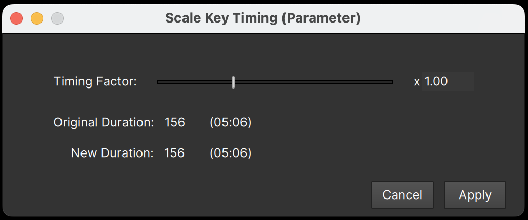
It shows you the original and scaled durations to help you decide on a scale factor, and as you change the Stage will update to show the results of the timing change.
If your emitter had other parameters that animate in relation to the position path – for example if the Number parameter increases so it peaks at the center of the position path motion then decreases again – then you probably don’t want to scale the animation timing of a single parameter. Instead, R-click the emitter node and select “Scale Emitter Animation Timing…”
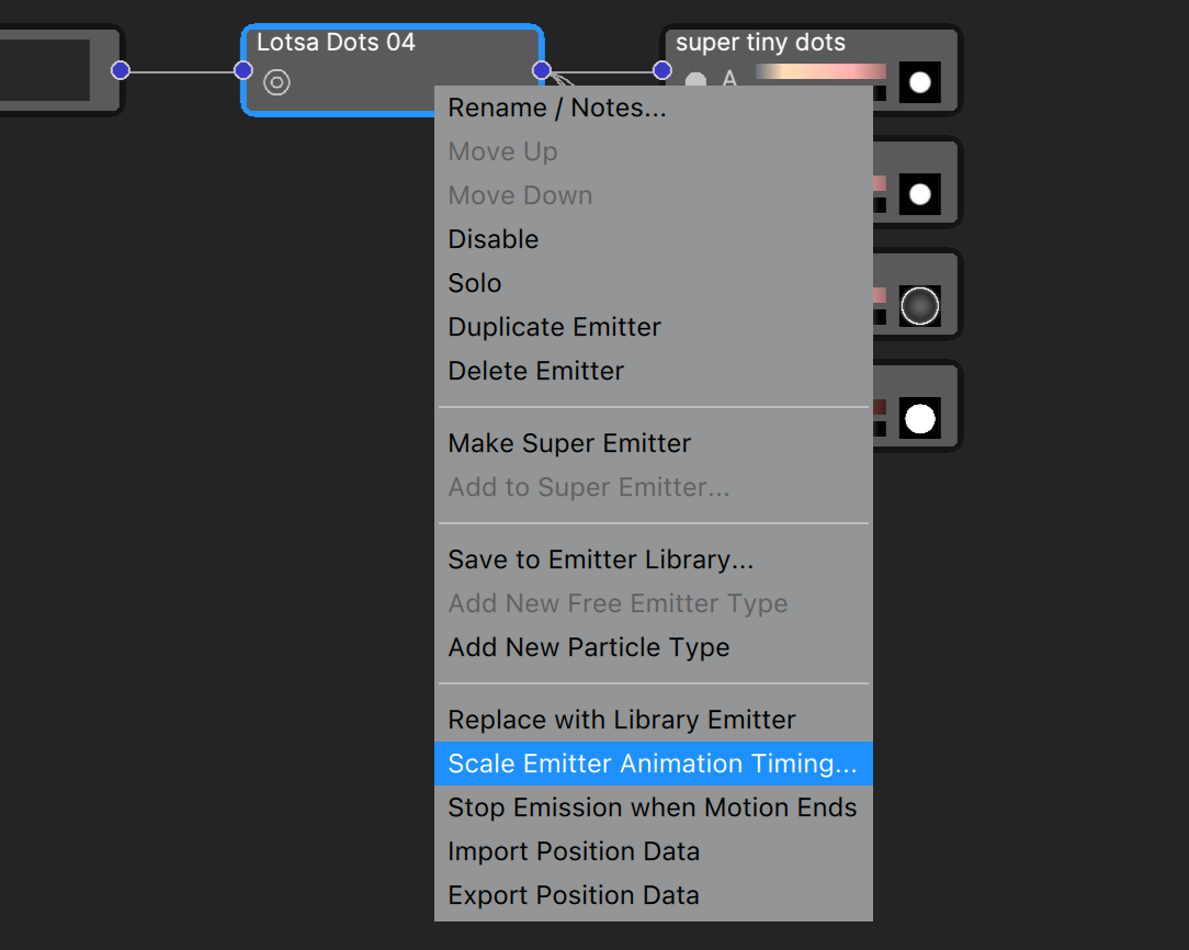
The same dialog will open, but 1) all animated parameters will be scaled, and 2) you won’t have a live preview of changes to the scale factor as you do when scaling the animation of a single parameter.
If your project contains multiple objects that have animated parameters, you’ll want to use the Action menu item instead:

This will scale the animation of all parameters, in all objects in the project.
Note that this feature, whether applied per parameter, object, or project, only changes the timing of animation frames – it does not adjust any parameter values.
Repeat Animation
Besides position path animation, many emitters contain other animated parameters – an “explosion” or “burst” style emitter has an animated “number” parameter for instance. What do you do if you want the emitter to “burst” multiple times? Yes, you could add multiple copies of the emitter offset in time, but then you have multiple emitters to adjust if any changes are needed.
Instead you can use the “Repeat Animation” function. R-click on any parameter that contains animation (including position and “over life” parameters, camera params – ANY animated parameter):
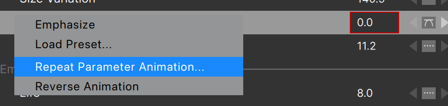
This opens the Repeat Animation dialog:
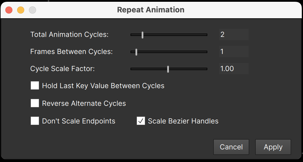
Here you can set the number of cycles, add a delay between repeats, scale the values, and more. The changes you make are shown in the graph view:
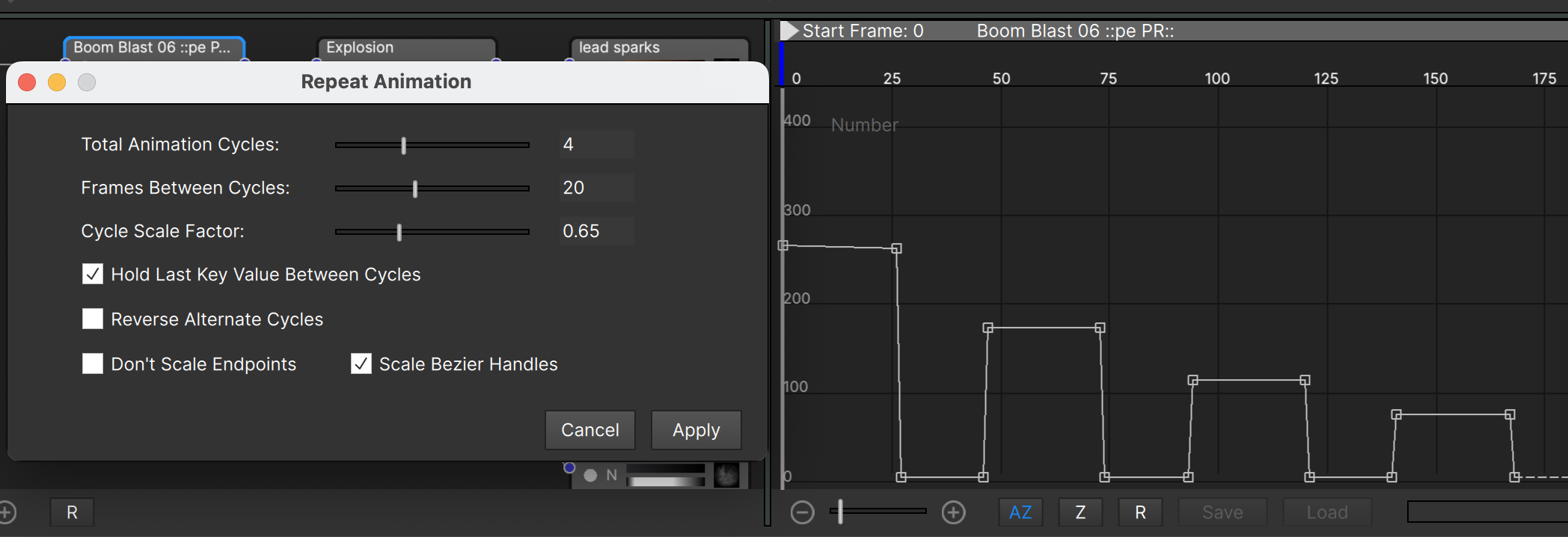
Here are details on each of the settings in this dialog:
- Total Animation Cycles: the total number of repeats of the animation. Note that it’s possible to extend the animation past the end of the project – you may need to adjust the project length after using this.
- Frames Between Cycles: the number of frames added between each repeat. Note that if you set this to 0 the intermediate key may be deleted (which is sometimes exactly what you want)
- Cycle Scale Factor: the scale factor applied to each cycle. (The same scale factor is applied to all keys in the cycle)
- Hold Last Key Value Between Cycles: If you’re adding frames between cycles, you’ll probably want to check this so that the last value of the cycle is held (by adding a key).
- Reverse Alternate Cycles: Flips the animation on every other cycle. This is especially useful for position path animation to make the emitter move back and forth along the path.
- Don’t Scale Endpoints: When checked the first and last keys won’t scale (if Cycle Scale Factor is used). This was added specifically for use with position paths.
- Scale Bezier Handles: Allows the handles to remain unscaled, which may be desired in some cases.
Note that all of the new keys the Repeat Animation function creates can always be modified just like any other keys, and it’s possible to use Repeat Animation multiple times in a row to create complex patterns quickly.
Reverse Animation
Suppose you’ve loaded a position path preset and have your emitter moving from left to right along the path (most of the path presets have motion that goes left to right) but you instead want the emitter to trace the path in reverse, from right to left.
Use the “Reverse Animation” function. R-click on any parameter that contains animation (including position and “over life” parameters, camera params – ANY animated parameter):
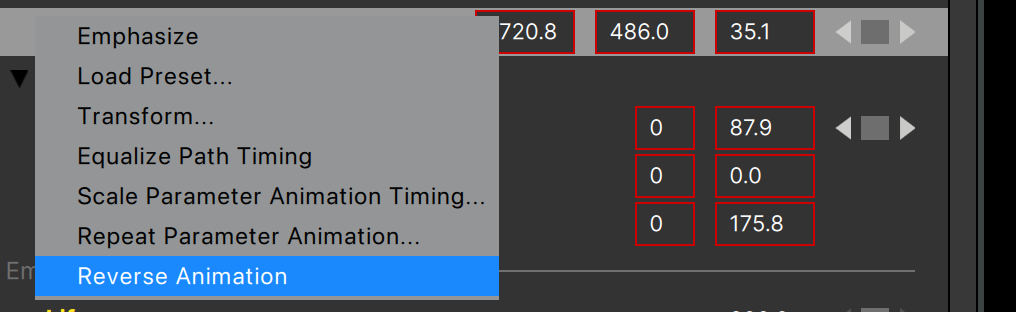
After selecting this function the animation is reversed.
Note that with position animation, using this function will not change the look of the path or the timing of the motion – the emitter will just move along the path in the opposite direction.
Before:
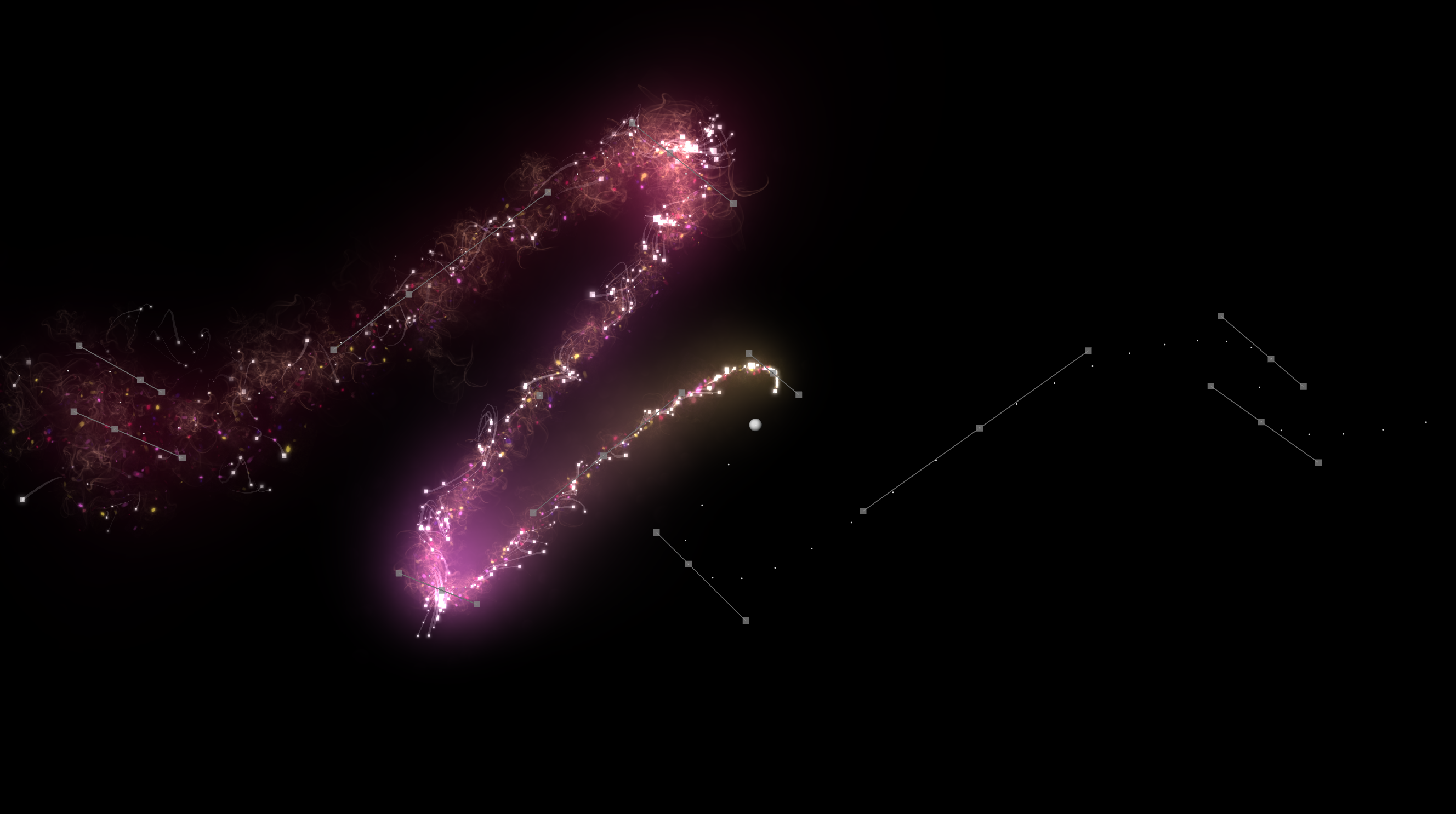
After:
Particle Type Properties
Back to the particle type parameters, the “Properties” group contains most of the low-level controls for particle types: how the particle is drawn, its color, and more:
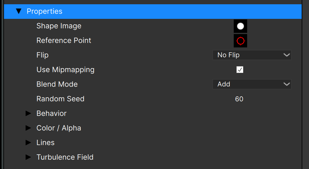
The “Shape Image” displays a thumbnail of the image (or “sprite”) used by particles of this type. Click it to change the image — but we’ll cover that in more detail shortly.
The “Reference Point” button brings up a dialog that allows you to change the reference point for the sprite, but that too will be covered more shortly.
The “Flip” option determines if the sprite (image) used for the particle is flipped horizontally, vertically, or both.
“Use Mipmapping”: When checked, smaller copies of the particle shape image (“texture”) are generated from the original, resulting in less aliasing in smaller particles. This is more apparent in particle shape images that have sharp edges. If your particles contain too much aliasing (jagged edges) when being drawn in smaller sizes, try checking this option.
The “Blending Mode” parameter determines how the particles of this type are composited. In older versions of Particle Illusion you could choose between “Intense” or non-intense, but now there are several options. Older projects will convert “Intense” to “Add”, and non-intense to “Normal”.
Here’s an example of the different blending modes using white particles, from left to right top row: Normal, Add, Screen, Subtract, Multiply; lower row L to R: Overlay, Soft Light, Darken, Lighten, Difference:

Notice that the particle nodes display an abbreviation of the blending mode used: “A” for “Add”, “N” for “Normal”, etc.
“Random Seed” allows you to change the randomization of a specific particle type. This is useful if you duplicate a particle type and want to give it variety.
There are five subgroups of particle type properties: “Behavior”, “Color”, “Alpha”, “Lines”, and “Turbulence Field”.
Particle Behavior
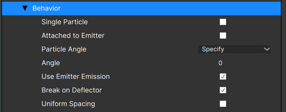
The “Behavior” group holds these properties:
“Single Particle”: when checked, a single particle of this type will be created. It will be connected to the emitter’s position (velocity and motion randomness will be ignored), and its life will be very long (on the order of 10K frames).
“Attached to Emitter” can be used when you want particles to move with the emitter, but don’t want just a single particle. When “Attached to Emitter” is checked, the attachment amount parameter becomes available — a value of 0 means that the particles won’t move with the emitter, and a value of 100 means that they fully move with the emitter.
The “Behavior” group also lets you set the particle angle. You can specify the angle (in degrees) and all particles of this type will be created at the same angle, you can select a “Random” angle, where you specify the angle range and offset value, or you can have the particles “Align to Motion”.
When aligned to motion you specify the rotation angle, and the particles will align themselves with their initial motion. If the particles have no initial velocity this may not work as expected.
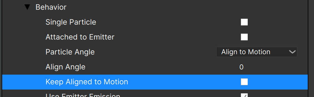
When the “Keep Aligned to Motion” option is checked the particle angle will continuously update based upon the particle’s motion – the particle should always point in the direction it is moving. Note that when this option is checked, the particle spin parameter will be ignored — “Keep Aligned to Motion” overrides the spin value.
The next parameter in the “Behavior” subgroup is “Use Emitter emission”. When checked, this particle type uses the emitter “Emission Angle” and “Emission Range” parameters. If unchecked, you’ll see “Emission Angle” and “Emission Range” parameters added at the particle type level. It’s not common to see this option unchecked.
The “Break on Deflector” option enables breaking of this particle type when hitting a deflector that is configured to break particles. When unchecked particles of this type will not break on deflectors. (Deflectors are covered later in this document.)
“Uniform Spacing” is the final parameter in the Behavior section and needs a little explanation. When an emitter is moving (its position is animated over time), particles will be created between the emitter’s position at each frame:
With the “Uniform Spacing” option unchecked, particles will be added at random positions as seen above. When “Uniform Spacing” is checked, the particles are added at regular intervals:
This option was added to allow “stroke” style emitters that leave a smooth trail of particles.
Particle Color and Alpha
The next subgroup determines the particle colors and transparency:
Clicking the color or alpha gradient brings up the gradient editor – we’ll discuss that shortly.
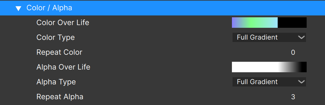
The “Color Type” menu allows you to select between:
- “Full Gradient”: the gradient represents the life of the particle, where the color at the left edge of the gradient is the color when the particle is born, and the right edge is the color when the particle dies. When this option is selected you have a “Repeat” value that can be used to repeat the gradient over the life of the particle.
- “Random Gradient”: a random color from anywhere on the gradient is chosen for the particle at its birth. The particle color does not change over its life. Choosing this option reveals a “Use key colors only” option, when checked the defined gradient colors are the only possible random choices.
- “Next key color”: A specified number X of particles of each defined gradient color are created, then the next gradient color is used for the next X particles, and so on. The number of particles created at each color must be specified.
- (Plugin version only) “Color from layer”: each particle gets its birth color from the source pixel beneath its creation position. The “Update Color from Layer” option means that the particle resamples the source image as it moves.
- “Map to Emitter”: Each particle gets its birth color from the gradient mapped to the emitter extents. There are three choices for mapping (see below).
- “Map to World”: Each particle gets its birth color from the gradient mapped to the world (frame). There are three choices for mapping (see below).
The alpha gradient shows the particle alpha over its life, and clicking the alpha gradient opens the alpha editor.
The “Alpha Type” menu allows you to select between:
- “Full Gradient”: the gradient represents the life of the particle, where the alpha at the left edge is the alpha when the particle is born, and right edge indicates the alpha when the particle dies. Note that white is fully opaque, and black is fully transparent. When this option is selected you have a “Repeat” value that can be used to repeat the gradient over the life of the particle.
- “Link To Color”: when selected the particle color gradient is converted to alpha values. (This option is not recommended as it does not work correctly in some situations)
- (Plugin version only) “Alpha From layer”: each particle gets its birth alpha from the source pixel beneath its creation position. The “Update Alpha from Layer” option means that the particle resamples the source image as it moves.
Color Gradient: Map to Emitter/World
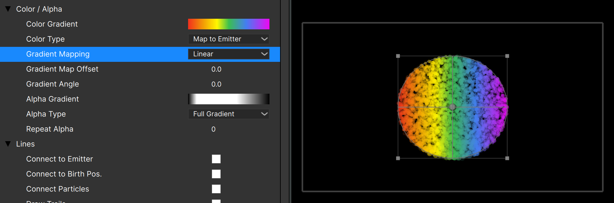
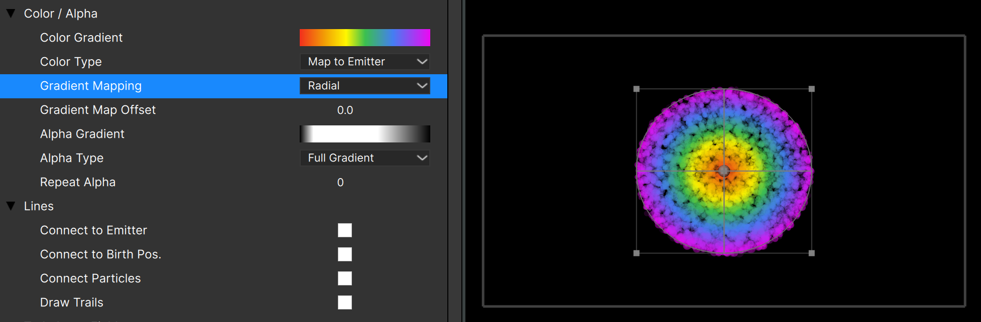
These options (new in v2026.5) provide a way to create large organic areas of color, resulting in more sophisticated, creative, and realistic effects:
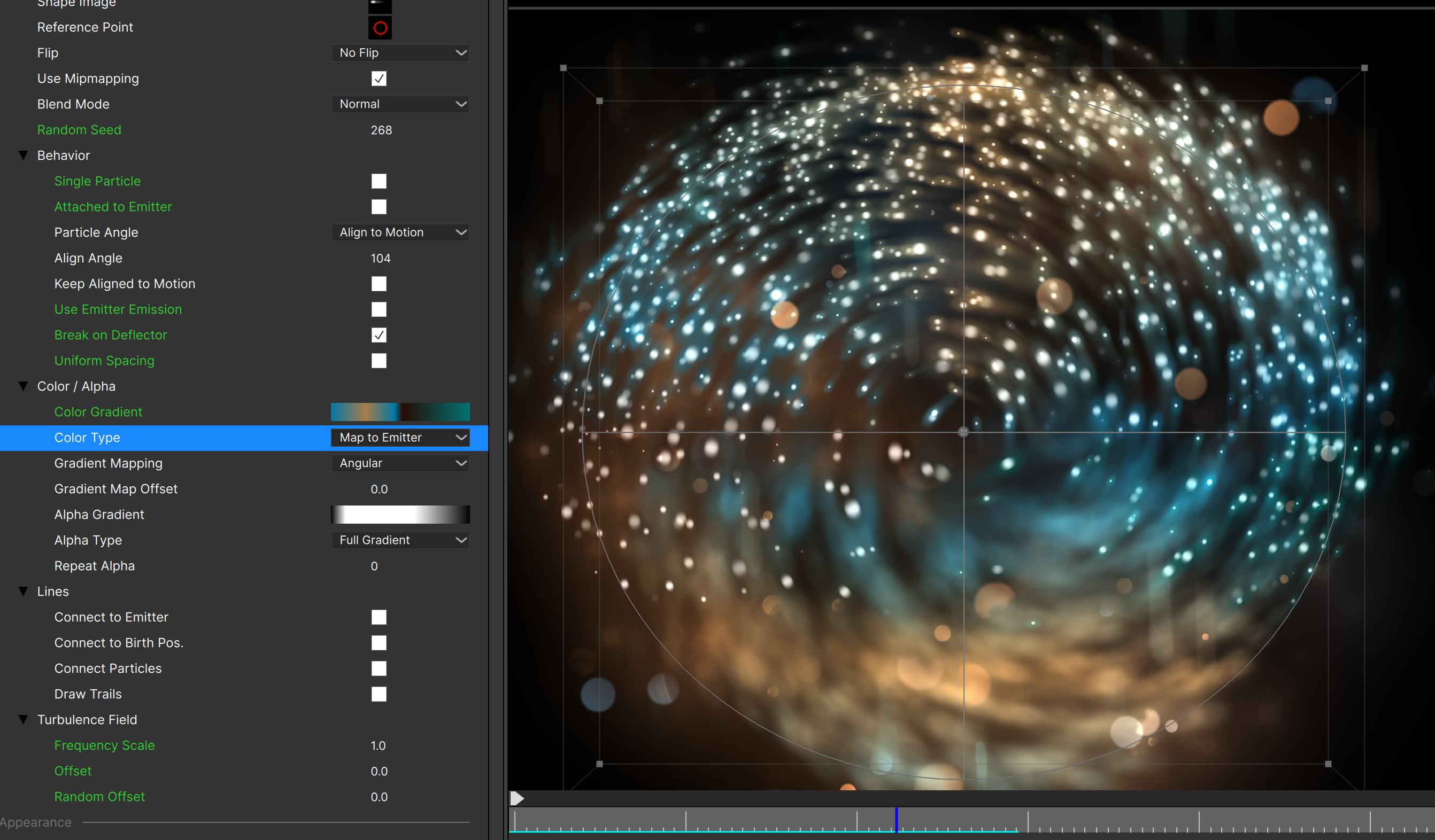
When using Map to Emitter or Map to World options, you can choose from three types of mapping: Angular, Linear, or Radial. Each of these is relatively straightforward but differs somewhat depending on the emitter shape (Line, Sphere, Box, etc.)
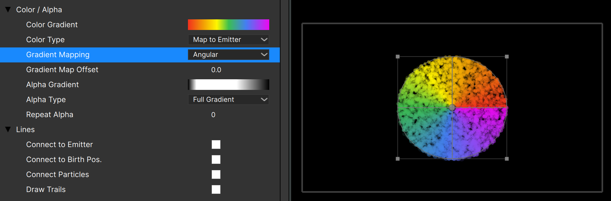
The results of Map to Emitter in each of the three modes can be different depending on the emitter shape (line, point, sphere, etc.) Most behave as you would expect with these noted exceptions:
- Line: The bounding box around the line points is used for mapping, with the emitter “center” point (the HUD point you can select and drag to move the entire emitter) being the center for angular and radial mapping.
- Point: All particles will be the start color of the gradient (since all particles are created at the exact same point) in all three mapping modes.
- Circle/Ellipse: In Radial mapping all particles will be the same color (they’re all the same distance from center)
- 3D Model: All particles will be the start color of the gradient in Linear and Radial mapping modes.
Map to World is very similar to Map to Emitter, but instead of using the emitter center and outer dimensions, the frame center and edges are used. The biggest difference from Map to Emitter is that emitter position also factors into color calculations in Map to World.
- Point: A stationary emitter will create particles all of the same color, but if the emitter position is animated a trail of colored particles will result.
- 3D Model: All three mapping modes produce expected results.
Each of the three mapping modes has parameters to rotate/shift the gradient:
- “Gradient Map Offset”: Sets the start point of the mapping. When set to 50 for instance, the middle of the gradient is the start point. In Angular mapping this appears to rotate the gradient, while in the other two modes it shifts it.
- “Gradient Angle”: (Linear mapping mode only) Sets the angle of the gradient.
One last reminders about these color gradient mapping modes: just like the other Color Type settings (Full Gradient, Random Gradient, etc.) this specifies the color of the particle at birth – the particle may move to another part of the frame but it won’t change color as it does.
Color Gradient Editor
Clicking the color gradient (or double-clicking it on a node) opens the color gradient editor:

The top gradient is the “resultant” gradient – the combination of the current color and alpha settings combined. It shows exactly what the particles will be doing over their life (only when using “Full Gradient” color over life option). Note that you can click the resultant gradient to toggle between different displays modes: on checkerboard, on black, transparent.
The gradient editor contains a number of buttons and controls:
Color chip: click to open the color picker
Revert button: restores the original gradient
Clear button: resets the gradient to all white and removes extra stops
Random button: assigns a random color to each of the stops
Flip button: flips/reverses the gradient
Space button: evenly spaces all stops
Loop button: makes a “looping” gradient by adding a copy of the first color stop to the end of the gradient. (Useful for Map to Emitter/World color types.)
Save Preset button: saves the current gradient as a preset
Load Preset button: opens the Color Presets dialog:
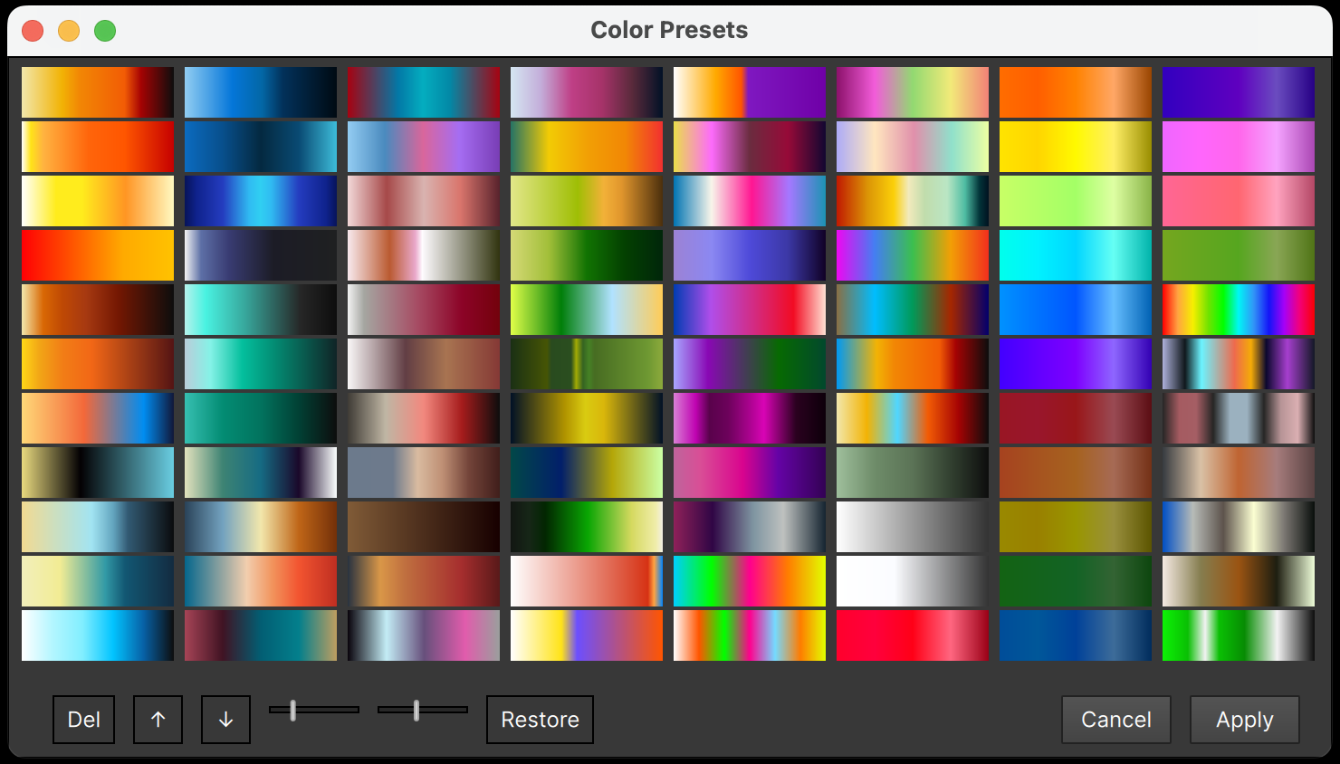
The gradient preset dialog, besides letting you choose a preset, allows you to reorder the presets by moving the selected preset up/down, delete the selected preset, and restore all factory presets (in case you deleted some and want to restore the full set).
The sliders allow you to set the size and shape of the presets too.
Note that tooltips show key shortcuts for these actions where applicable.
After choosing a preset, you can continue adjusting as needed. There are a few remaining controls in the gradient editor to discuss:
H slider: adjust the Hue of the entire gradient at once (all stops)
V slider: adjust the Value (brightness) of the entire gradient at once
S slider: adjust the Saturation of the entire gradient at once.
These sliders should be used as a last step in the process, as once you’ve changed them some of the other changes you make can be unpredictable.
Gradient Editor Key Shortcuts
The gradient editor has undo/redo capability using Cmd-Z, Shift-Cmd-Z (Ctrl-Z, Ctrl-Y on Windows) for everything except the HSV sliders.
Also, when a color stop is selected, you can use key shortcuts to tweak the stop:
Right/Left arrows: adjust Hue of the selected stop
Up/Down arrows: adjust Saturation of the selected stop
Alt/Option-Up/Down arrows: adjust Value (brightness) of the selected stop
Alpha Gradient Editor
Clicking the alpha gradient (or double-clicking it on a node) opens the alpha gradient editor:
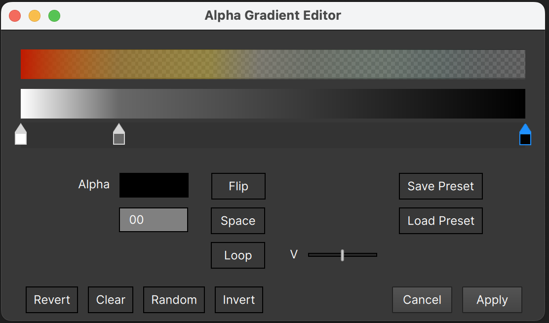
It’s almost identical to the color gradient editor, but has no H or S sliders, and adds an “Invert” button which inverts the value of each stop in the gradient. It also shows the resultant gradient, so you can see exactly how the alpha changes will be applied.
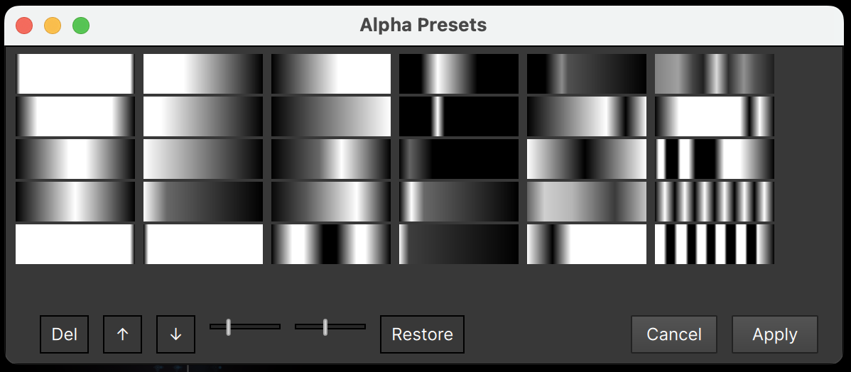
The “Load Preset” button opens the Alpha Presets dialog:
Particle Lines
The “Lines” subgroup allows you to connect the particles with lines in various ways.
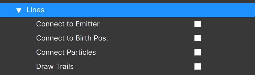
There are four different ways to connect particles with lines; they can be used independently or in combination:
“Connect to Emitter”: draws lines from the particles to the emitter’s reference point.
“Connect to Birth Position”: draws lines from the particles to the position they had when first created. For point emitters that are not moving this gives the same results as “Connect to Emitter”, but for moving emitters or all other emitter types this will look very different from “Connect to Emitter”.
“Connect Particles”: draws a line from a particle to the previous particle. Since the “previous particle” can possibly be quite a distance away from the current particle — with area emitters for instance — once “Connect Particles” is enabled, a “Max Line Length” parameter becomes visible:
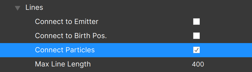
Use this to limit the lines that are drawn when connecting particles. Only lines that are below this limit will be drawn.
If you have a case where turning on “Connect Particles” results in a wild tangle of lines, try decreasing the “Max Line Length” value.
The final line option is “Draw Trails”. When checked, lines will be drawn to each particle’s position at previous frames, tracing the particle’s motion path with a trail. There are a few options for line trails:
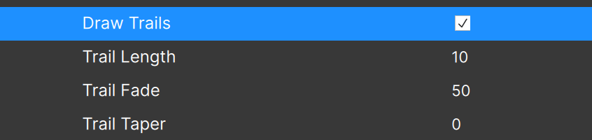
“Trail Length”: Determines how many previous positions are used.
“Trail Fade”: How much of the trail is faded out to 0 opacity. A value of “50” means that the fade starts at 50% of the trail length. Note that the fade won’t be smooth for very short trails.
“Trail Taper”: How much of the trail will taper to 0 width. A value of “50” means that the taper starts at 50% of the trail length. Note that the taper won’t be smooth for very short trails, and is more visible when using thicker lines.
The other line parameters relate to how the lines themselves look: their thickness, color, and opacity. They only become visible when one of the line options is enabled:

The “Intense (Add)” checkbox lets you make lines intense (additive) when the particles are not, or non-intense (“Normal”) when the particles are. This can really help clarify some emitters by avoiding “wash out” with too many “intense” items.
Although the “Thickness” value can be set to any value between 0.0 and 100.0, you may find that only specific values make a visible difference when 2D lines are being used. This is entirely based on your hardware and or graphics driver — for instance a value of 0.5 might look exactly like a value of 0.9, then 1.0 will increase the visible thickness. Integer values should always work (we haven’t found a case yet where they don’t), so it’s probably best to stick to whole numbers when designing emitters using 2D lines.
Note that the antialiasing (smoothness) of lines may also be completely hardware or graphics driver dependent.
When using 3D lines (set in the Emitter Properties section), these limitations in thickness, antialiasing, etc. do not apply.
“Size Scales Thickness” adjusts the thickness of lines based on particle size. (Applies only when the “Size Variation” of the particle type is non-zero.) This works best with thicker lines.
For Line Color there are two options: “Use Particle Color”, which is self-explanatory, and “Specify”, which lets you set the color independently of the particles. Note that even when you select “Specify”, if the emitter has a non-zero Tint Strength, the Tint Color will be applied to lines as well as particles.
Line Opacity also has two options: “Scale Particle Alpha” and “Specify”. If the particles have an alpha that changes over time, you may want to use “Scale Particle Alpha”, as the line opacity will be the result of the “Opacity” value (set here in the “Lines” section) multiplied by the current alpha of the particles. If you want the lines to fade out with the particles, use this option.
If instead you want to the lines to remain at a constant opacity regardless of what the particle alpha is doing, use the “Specify” option. Note that with this setting lines will abruptly disappear when the particle dies.
There is one last option that shows only when using “Connect to Emitter” or “Connect to Birth Position”:
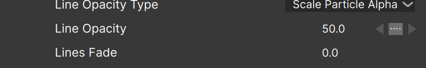
When “Lines Fade” is set to a positive value, the start of each line is faded. This can help avoid situations where you get the “starburst” of lines converging to a point.
When “Lines Fade” is set negative, the end point of each line is faded.
In this example, the left is Lines Fade = 0, middle is Lines Fade = 100, right is Lines Fade = -100:
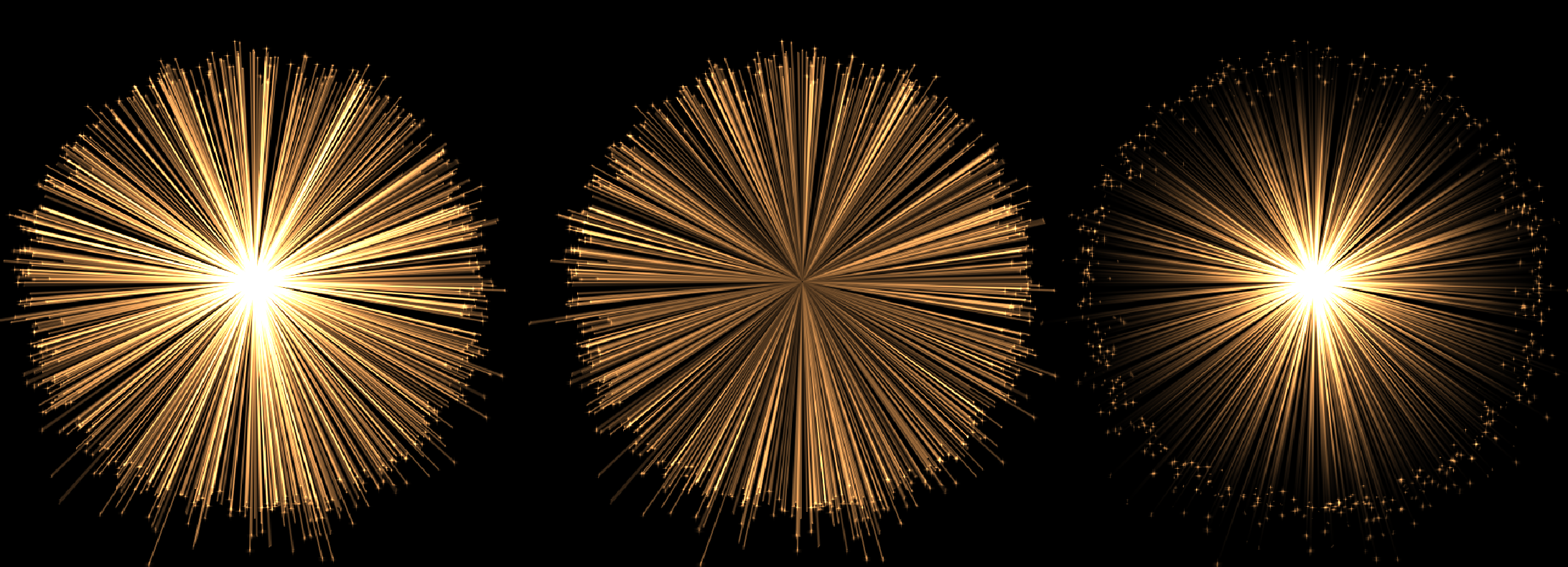
Although the appearance of particle lines is often dependent upon your specific graphics hardware and/or driver (when using 2D lines), you’ll find that lines are an important addition to many particle creations!
Creative Tip: If you want lines only but don’t want to see the particles, set the particle “Size” value to 0.
Particle Turbulence
The final subgroup is the “Turbulence Field” group:
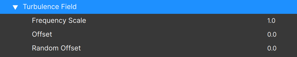
The parameters in this group allow you to adjust the noise field of each particle type individually. Remember that the base Turbulence Field settings are made in the Emitter Properties, and by default each particle type in the emitter will use the same settings.
“Frequency Scale” is an additional multiplier to the base Frequency. Higher values result in higher frequencies (a smaller noise pattern in general).
“Offset” allows you to use a different portion of the turbulence field, giving these particles a different turbulence look without changing the frequency.
“Random Offset” gives a random offset amount to each individual particle. Large values result in chaotic noise that loses its organic feel, but smaller values can “smooth out” the turbulence pattern and soften the final look.
Changing Particle Shape Images (“Sprites”)
When you click the “Shape Image” thumbnail (or double-click the thumbnail on the particle node), the Shape Editor dialog opens:
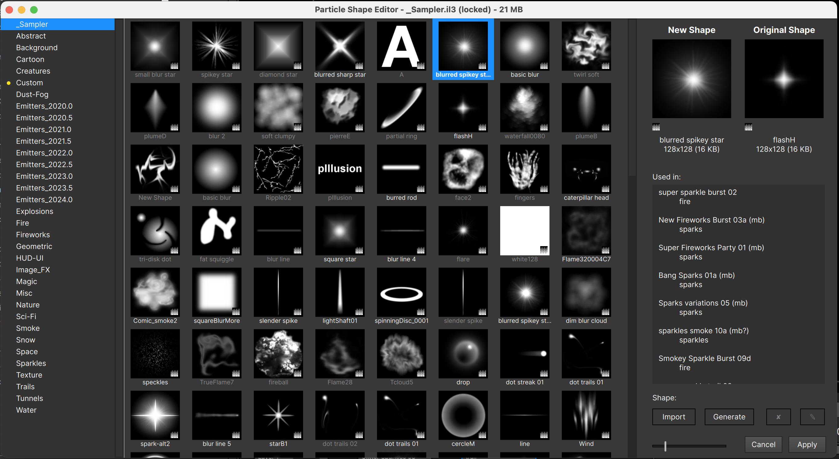
This dialog lets you:
- Select a new shape from those available in any of the available emitter libraries
- Import a shape from an image file
- Generate a new image using AI
1. Selecting from Available Sprites
As you select a shape from those available, the “New Shape” thumbnail will give you a larger preview of the selected shape, but more importantly the particles in the Stage are updated. (You can open the Shape Editor dialog while playback is occurring so it’s possible to see the particles in motion.)
The dialog opens with the shapes from the currently active emitter library, but you can select any other library on the left to choose from the shapes available there.
The right part of the Shape Editor displays useful information about the selected sprite/image, specifically:
- The total approximate memory footprint of the selected library (shown in the title bar)
- The approximate memory footprint of the selected shape
- The emitters that are using the selected shape (in the scrollable “Used in:” window)
If the “Used in:” window is blank, the selected shape is not used in the selected library.
Note that in the display grid of shapes, any unused shapes will have their name dimmed, so you can tell at a glance which shapes are not being used – which can be helpful when creating your own libraries if memory usage or library file size is a concern.
The “Shape:” area contains the “Import”, “Generate”, “Delete”, and “Rename” buttons.
The “Delete” button only enables when an editable library is selected (more on this in another section). The title bar of this dialog indicates not only the library name, but whether or not the library is locked, and the approximate memory usage of the library.
The “Rename” button is again enabled only when an editable library is selected, and allows you to rename a shape that you’ve added.
2. Importing from Image File
The “Import” button is used to select an image file. Several image formats are supported: BMP, HEIC, HEIF, JPG, JPEG, JP2, PNG, TIF. After selecting the image file the Import Particle Shape dialog shows:
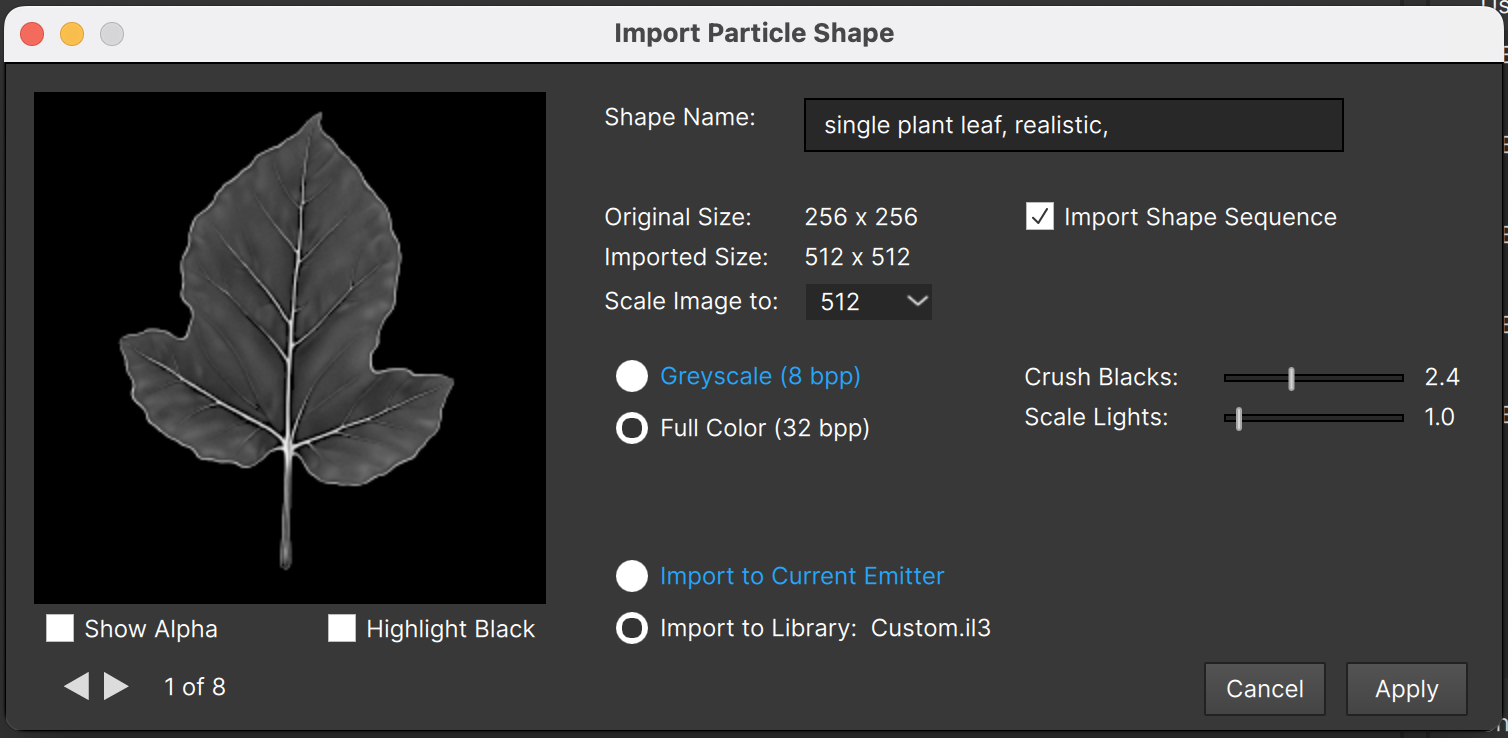
It looks like there is a lot going on here, but there are two main decisions you need to make: image size, and whether to create a “Greyscale” or “Full Color” sprite.
Image size is set by the “Scale Image to:” value. Although Particle Illusion will let you choose a larger size than the original image, you’ll get best results when using the same size or smaller – which is why the “Original Size” is indicated.
The intended use for the sprite is critical when determining the size. If the sprite will only be used by tiny particles like dust, sparks, or sparkles, then there’s no reason to select a larger size. If instead you will, or might, use the sprites for large particles like smoke, motion graphics elements, or anything similar, you’ll want to import large. Large sprites use much more memory, which is the main concern when selecting a size – it’s especially important when importing multiple frames.
If you’re importing for the current emitter only and this won’t be added to a library, the choice is less important, but unecessarily large textures will bloat your project size – including your host project size if running as a plugin, and could use more memory than it needs to.
The guidelines that we use when creating emitters for release (in a library):
- Use 256x256 for anything that will mainly be used at a small size
- Use 1024x1024 if the sprite will be shown very large – but only if one (or a few) frame(s)
- Use 512x512 as a compromise for medium/larger sprites or multiple frames
Since you have the original images, you can try importing at different sizes and see how it works in your project. It’s not really possible to have a sprite that is “too big” since it will be scaled down cleanly (especially if MIP mapping is used) – as long as memory is not a concern, but there is an obvious visual artifact if the sprites are too small for their current use: they will look very soft or blurred, with lack of detail and possibly visible pixelization.
The second choice you’ll need to make when importing is whether it will be a “Greyscale” sprite, or “Full Color”. What’s the difference? How do you choose?
Greyscale sprites are 8-bit, single channel, so hold no color information. An alpha channel is generated from the grey values: white pixels are fully opaque, black pixels are fully transparent. If you don’t need the sprite’s original colors, then “Greyscale” is the best choice. It’s especially good for smoke, sparkles, or similar. (Basically, use this unless you really need to retain the sprite original colors.)
Full Color sprites are 32-bit RGBA. Note that these sprites do not always show particle gradient colors or emitter tint colors accurately (tinting a green leaf sprite red for instance probably won’t give you a red leaf). Note that particles that use Full Color sprites but are flagged as “intense” actually use a Greyscale version of the sprite – the color information isn’t used. (This means a sprite imported as “Full Color” actually use 4 or 5 times the memory of the equivalent sprite imported as “Greyscale”.)
Remember that the approximate memory used by a sprite after importing shows below the preview in the upper left of the Particle Shape Editor – you can use this to verify that the sprite you’ve imported has reasonable memory usage. (Usually on modern machines and OSes, this is not a huge concern. It’s worth checking into if you start seeing memory-related issues though.)
After selecting the size and type of sprite, there are a few details like naming the shape/sprite and selecting where the sprite should be used. If the current emitter library is one that can be edited (is unlocked), then you’ll be able to choose between importing this shape into the library, or just applying it to the current emitter. If the library is locked you’ll only be able to import to the current emitter.
Note that both here and in the Particle Shape Editor the transparency of the sprites can be shown via checkerboard in all of the large previews. You can click the preview itself to toggle the transparency on and off — or here you can use the “Show Alpha” checkbox.
Importing a Sequence
If you want to import a sequence of images to use for the particle sprites rather than a single image, the files must be named as a sequence with a number at the end. For instance, “blur_round_00.jpg”, “blur_round_01.jpg”, “blur_round_02.jpg”, etc. If Particle Illusion detects that the selected image is part of a sequence, it will allow you to import the sequence instead:
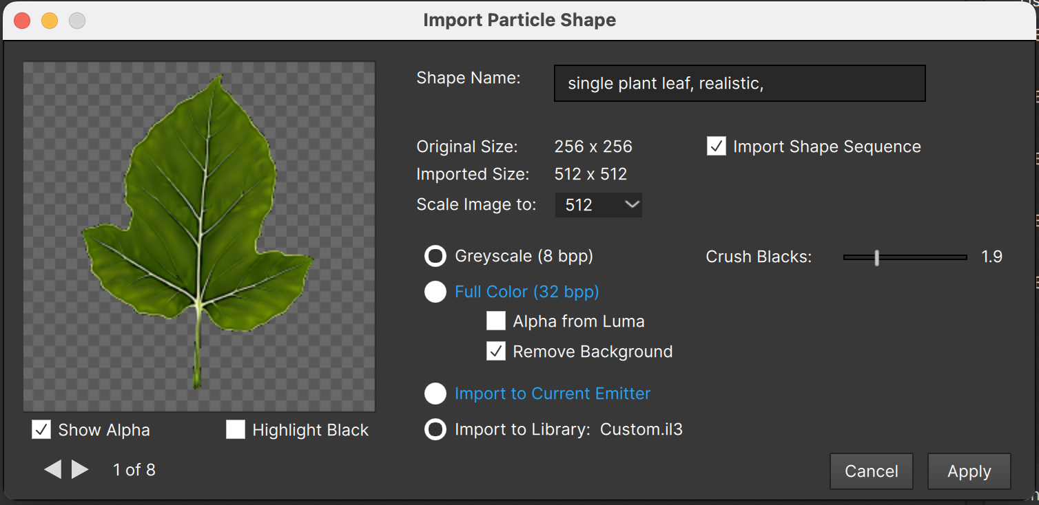
When the sprite contains multiple frames, you can use the arrow keys below the preview to switch frames, or you can just scroll when your mouse cursor is over the image (using your mousewheel or trackpad scroll gesture).
Note: if you uncheck the “Import Shape Sequence” option when a sequence is detected, only the first image of the sequence will be used – NOT the exact image you selected.
Full Color: Creating Alpha
As mentioned earlier, Greyscale sprites always create an alpha channel. It’s also possible to create alpha for Full Color sprites using one of two options:
“Alpha from Luma”: Uses the luma values for alpha. The “Scale Lights” slider can be used to make light areas less transparent, and “Crush Blacks” will make near-black pixels darker.
“Remove Background”: If the image has a black background this option will remove it but can also preserve interior dark details in the image itself. (“Alpha from Luma” will make those dark interior details transparent). Use “Crush Blacks” for more control.
Clean Black Background
In order to have a sprite with no “border edges” showing, you’ll want to ensure that the alpha is 0 at the edges, and if you’re creating the alpha from the image here that means the background must be completely black (RGB 0,0,0) at the edges. The “Highlight Black” option below the preview will help with this:
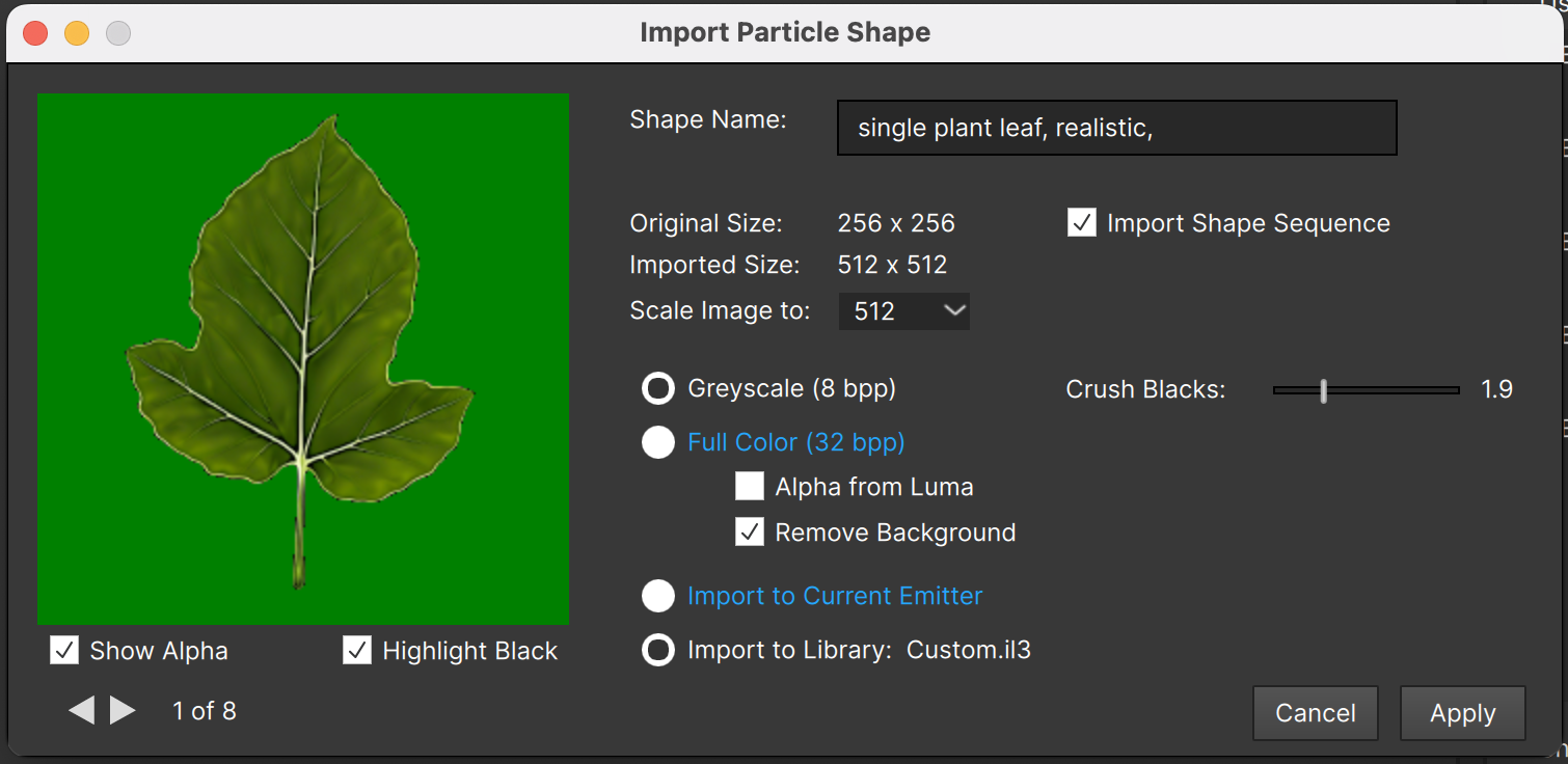
When checked, “Highlight Black” makes all of the fully black (RGB 0,0,0) pixels bright green so that it’s obvious when the edges of your image are not black.
Use the “Crush Blacks” control to clean up any noise in the background too.
3. Generate Using AI
The third function of the Particle Shape Editor allows you actually generate (create) new sprites using Stability.AI’s Stable Diffusion.
Click the “Generate” button to open the Generate Particle Shape dialog:
![]()
The first time you open this, you’ll be guided through a couple of setup steps. The red text indicates that you need to enter an “API Key”.
Sprite generation in Particle Illusion uses Stable Diffusion, which requires a third-party Stability.ai account (not affiliated with Boris FX in any way). You need “credits” to use this feature, and creating your Stability.ai account gives you a small number of them for free, or you can purchase additional credits - they are not expensive.
Your Stability.ai account page will show your API Key(s) - copy one and then paste it here and click the “Acct Info” button as indicated:
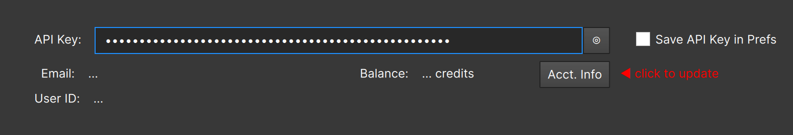
You should see the account information update with your email address, user ID, and credit balance.
Check the “Save API Key in Prefs” option if you want it to be automatically entered for you each time. Note that it stored in your preferences unencrypted, but it is a simple thing to invalidate your API Key at your DreamStudio account page and create a new one if you ever think that’s necessary.
How Sprite Generation Works
Generative AI typically relies on text prompts that describe the result you’d like, with other settings to determine how accurate the results need to be, what artistic style to use, etc. In Particle Illusion you always start with an existing sprite – a “seed image” – that is used as a starting point for the Stable Diffusion generator. This “seed image” makes it much easier to get the results you want in a format that is useful as a sprite – most notably the black background.
When the Generate Particle Shape dialog opens, whatever sprite was currently selected is used for the “seed image”. If you don’t select a sprite before opening this, the first sprite of the current library will be used.
We’ll detail each of the different parameters shortly, but an easier way to jump into this is to click the “Load” button in the “Presets” area, which opens the Particle Shape Generation Presets dialog:
![]()
In this example we selected and applied the “Cartoon Grass, Detailed” preset. Loading a preset updates all of the settings, including the seed image. You’ll notice that there is already a “Generated Image” shown even though we haven’t actually generated anything – that’s the preset thumbnail image:
![]()
When you click the “Generate” button, Particle Illusion will send the image request to the servers and wait for the images to be returned:
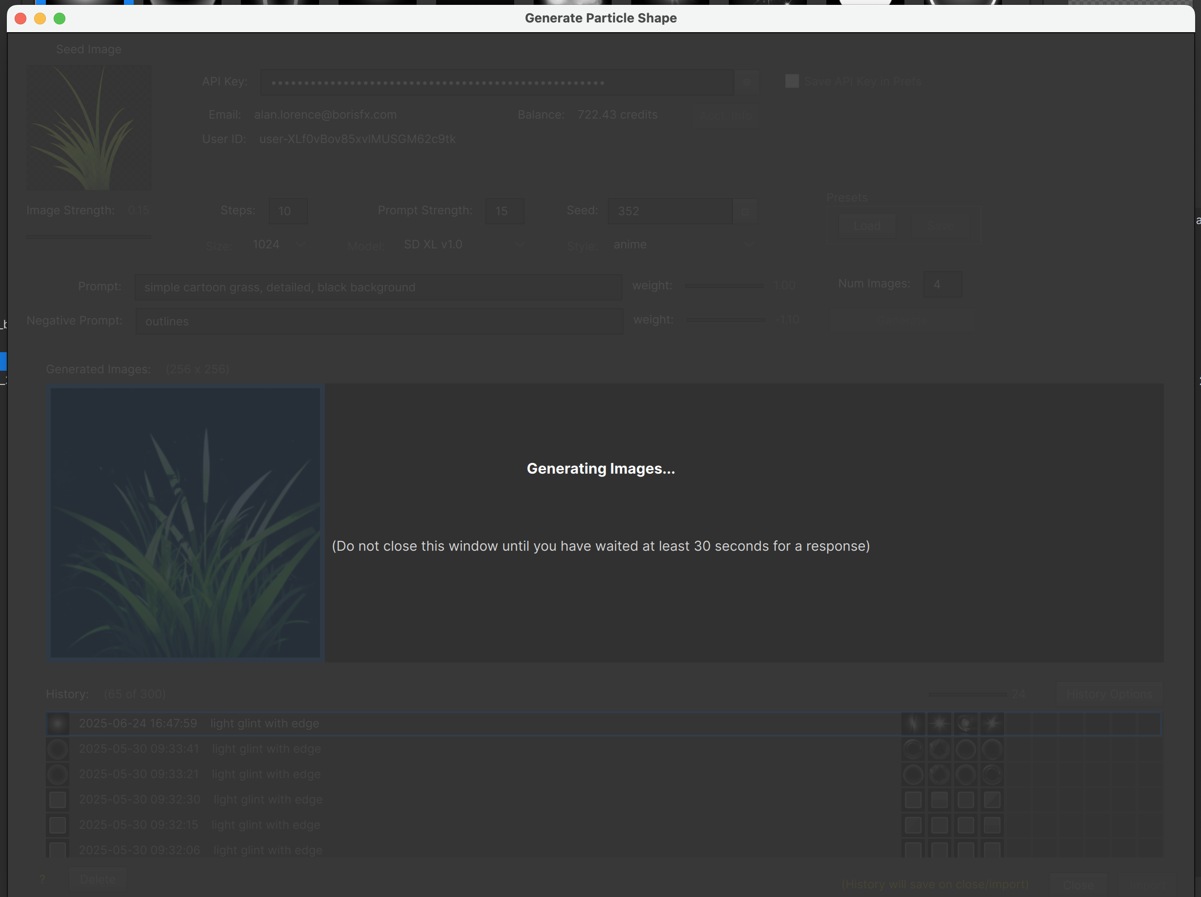
This can take anywhere from 3 to 30 seconds (or more) depending on the settings, number of images to generate, connection speed, server load, etc.
If the “Generating Images…” prompt stays for a minute or more – whenever you’re certain that something is not right – you can manually close this window using the “X” button in the window title bar and try again.
When the images are received from the server, the window is re-enabled and your results are displayed:
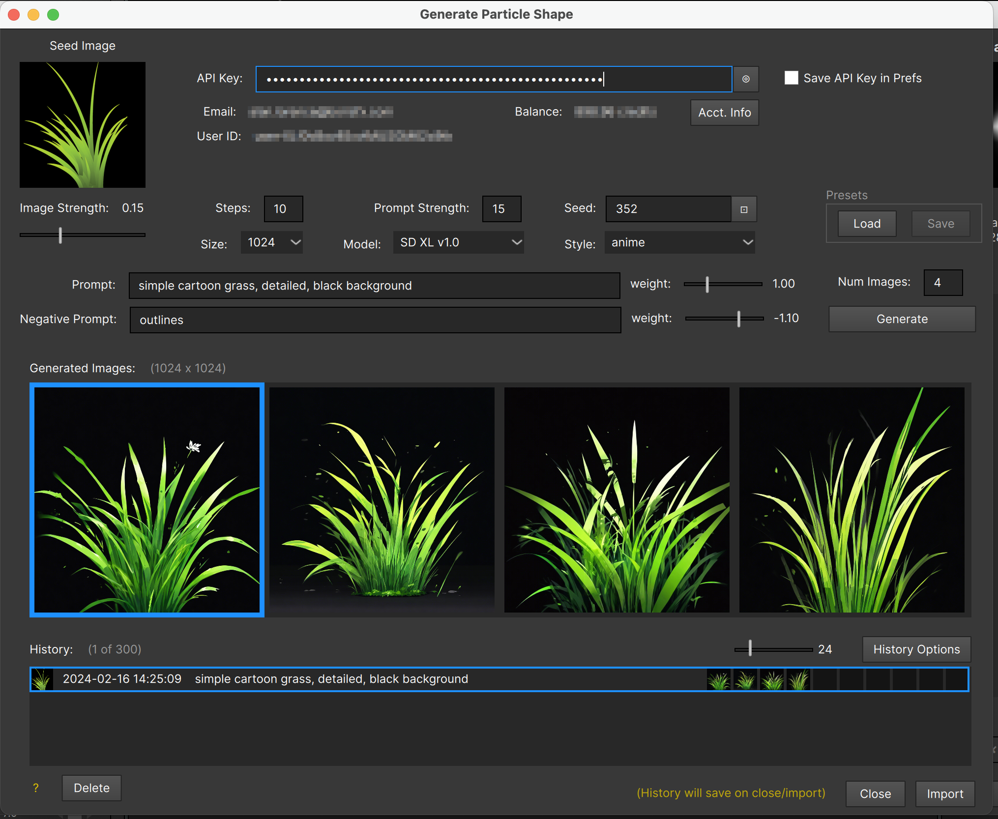
You can now select any of the resultant images and click the “Import” button to close this window and start the sprite import process, which works exactly the same as if you were importing from an image file (see above).
If you’re not happy with the results, you can change any of the settings (like “Seed”) and click “Generate” again to get a new set of images. Note that if you don’t change any setting and just click “Generate” again, you should get back identical (or very nearly so) results, but the order of the returned images will probably have changed.
Experiment Without Fear
Even if you decide that generating a sprite isn’t what you want at this time, just click the “Close” button to get back to the Particle Shape Editor button. The next time you open the Generate Particle Shape dialog you’ll resume almost exactly where you left off – you won’t have lost anything.
I say “almost” exactly where you left off because the seed image will have updated to whatever was selected when you opened this dialog – that’s the desired workflow so you can quickly try different sprites for seed images.
If you really do want to use every one of the settings you had previously, including the seed image, the History keeps all of your previous generate results, including a scaled version of the resultant images:
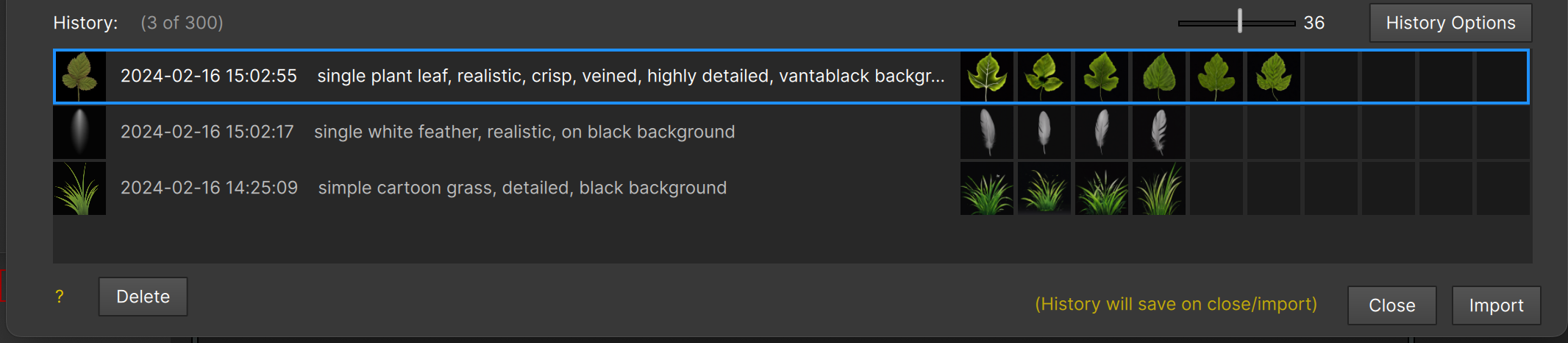
Select any history item and all of its settings are restored, including the generated images. The images stored in the History will probably be smaller than freshly-generated images, but may still be a useful size-as is.
Set the size of images in the History in the History Options:
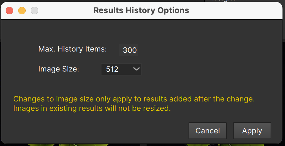
The larger the history images are, and the greater the number kept, the larger the history file will get – and the longer it will take to save it whenever it changes. (It only saves upon close of the Generate Particle Shape dialog).
As indicated in the History Options dialog, changing the image size will only change hitory items saved after the change – it does not resize all previous images.
If you rarely use history images directly for importing, you may want to set the history image size to 256 or 128 – that will greatly reduce the size of the history file.
Sprite Generation Settings
Let’s take a look at each of the settings for image generation:
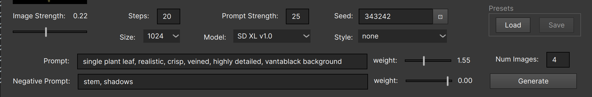
Each of these displays a tooltip when hovered over, but here’s more detail on each.
Image Strength: How closely the seed image should be followed. When set to 0, ignored the image completely (not recommended). Values around 0.10 - 0.15 are usually good starting points.
Steps: How many “diffusion steps” to run – essentially “iterations”. Higher values use more credits and may result in more realism or details, which is not always desirable for sprites.
Prompt Strength: How closely the Prompt is followed. Values around 20-25 seem good.
Seed: The random noise seed. Must be non-zero if you want to save a preset.
Size: The size of the generated image. Don’t change this unless you get an error message saying that you need to (after you change model).
Model: The engine to use. You’ll probably never change this, but note that this list may change in future updates as new engines become available.
Prompt: The text that describes what you want to generate. This is required. It’s best to keep this relatively simple, but remember that it won’t understand everything. (For instance, try to get it to generate a single piece of popcorn. Good luck!) The “weight” determines how strongly to follow these.
Negative Prompt: The description of things you don’t want to see. Best to leave this empty and only add things as they show up in your results. For instance, you can use this to try and keep a “shadow” or “stem” out of the generated images. The “weight” determines how strongly to follow these – set to “0.00” to ignore the Negative Prompt.
Num Images: How many images to generate. You may want to keep this low when experimenting, but a single image may give misleading results – it may be the one “bad” image of the current settings. If you generate more than 4 images, the Generated Images window can be scrolled (even though there is no visible scroll bar).
Style: The artistic style to apply when generating. Typically you’ll want to keep this as “none”, although some of the styles are quite interesting, and it’s fun to experiment.
Here’s the leaf example from one of the Sprite Generation Presets set to various styles. In each case all other settings were the same – only the “Style” changed. (The returned images are not always in the same order.)
Style: “None”

Style: “Photographic”
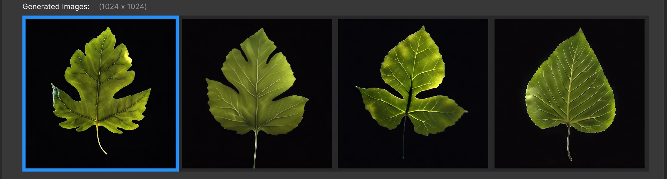
Style: “Line-Art”
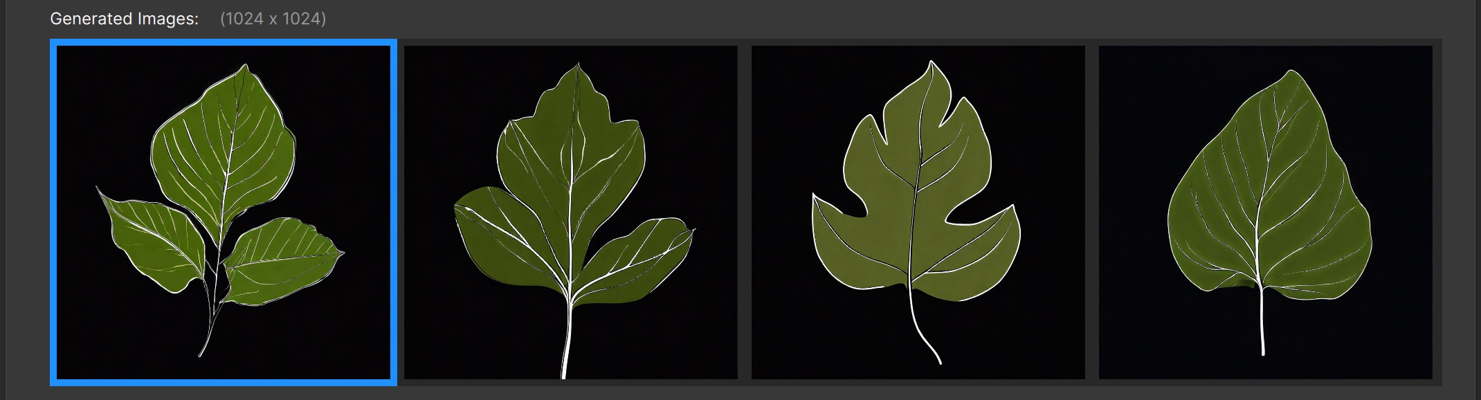
Style: “Anime”
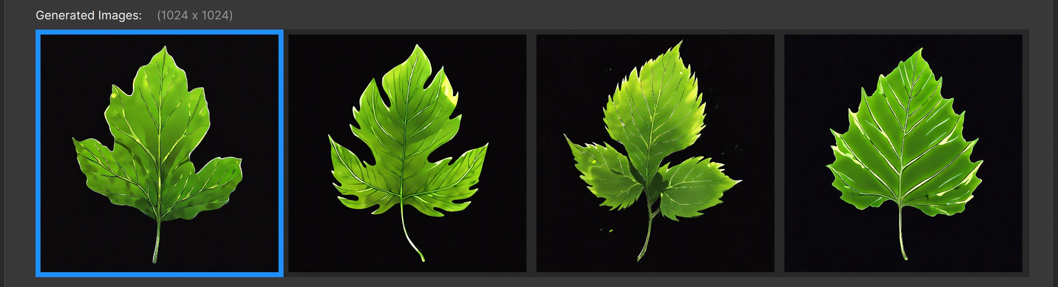
Style: “Fantasy-Art”
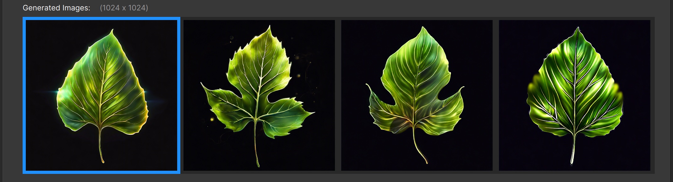
Style: “3D-Model”
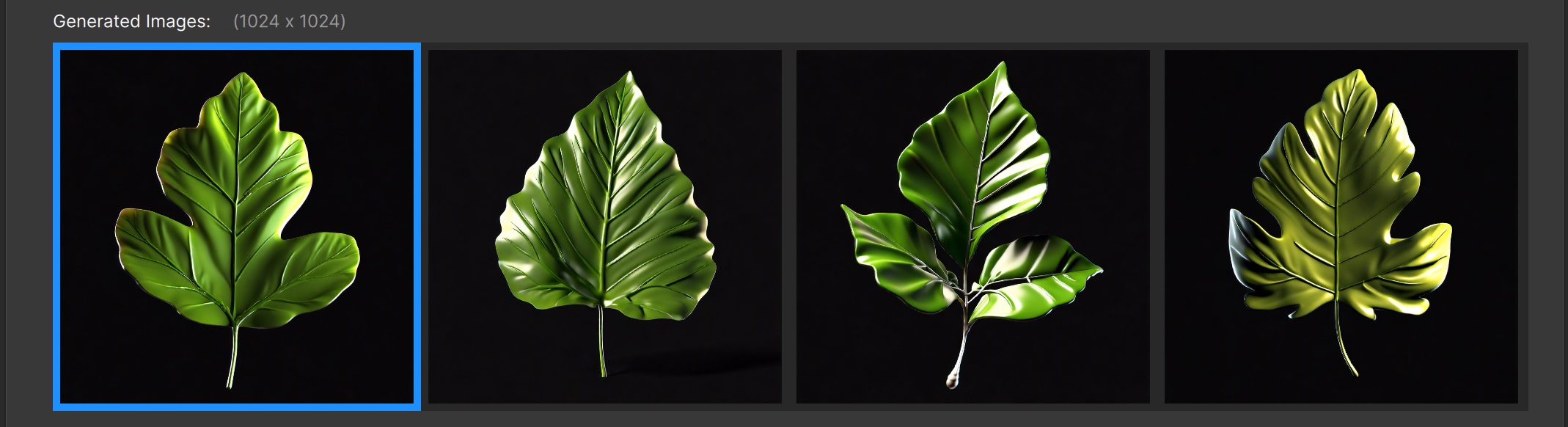
Style: “Low-Poly”
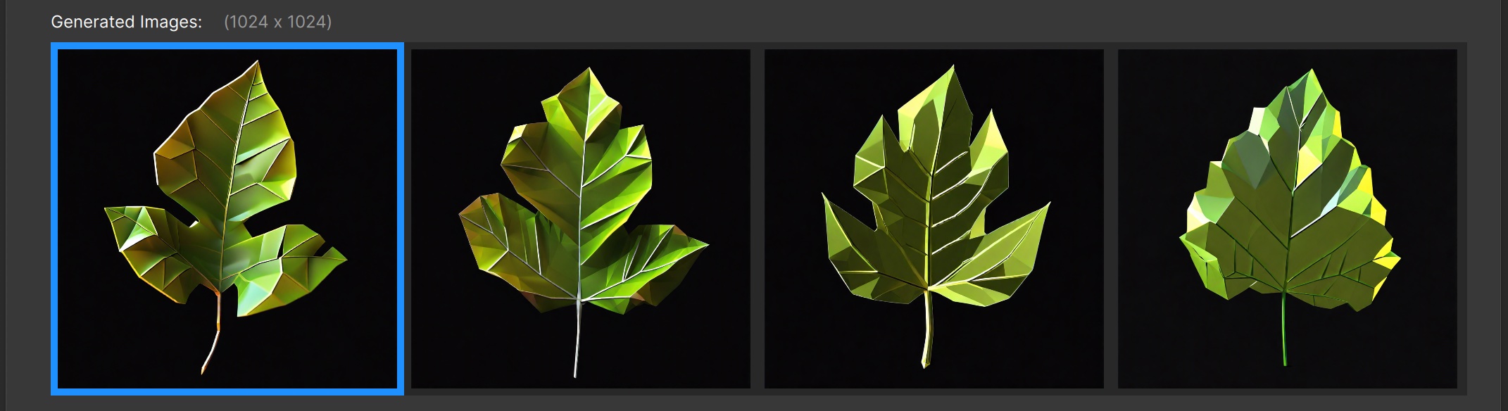
Style: “Modeling Compound”
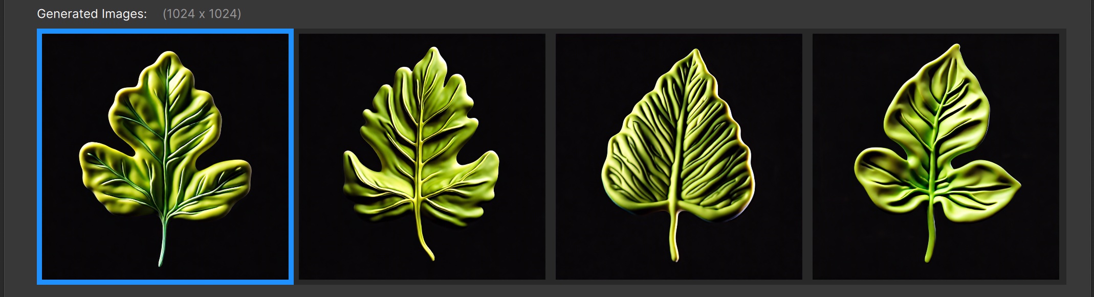
Style: “Origami”
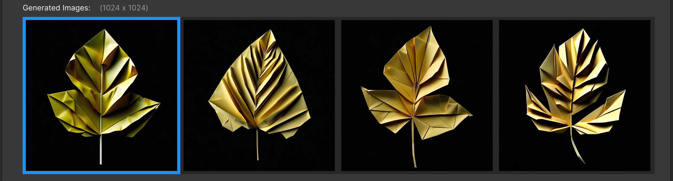
Style: “Pixel-Art”
![]()
Some Styles will add unwanted effects (not useful for sprites), for instance “Cinematic” seems to always want to simulate a short depth of focus, resulting in blurring parts of the image – even if it doesn’t make sense.
If you’re having a hard time getting rid of some stylistic feature and the Style is not set to “None”, try changing it to that to see if it helps.
The ability to generate sprites (added in the 2024.0 version of Particle Illusion) is a huge leap forward in creativity and utility.
Reference Point
The “Reference Point” for a particle is the point at which scaling and rotation happens. Most of the time this reference point is set to the center of the particle shape/sprite, but it’s often useful to move that reference point — you can do this by clicking the red circle “Reference Point” icon in particle properties:
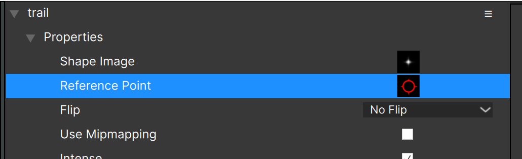
The resulting dialog lets you click and position the reference point wherever you want:
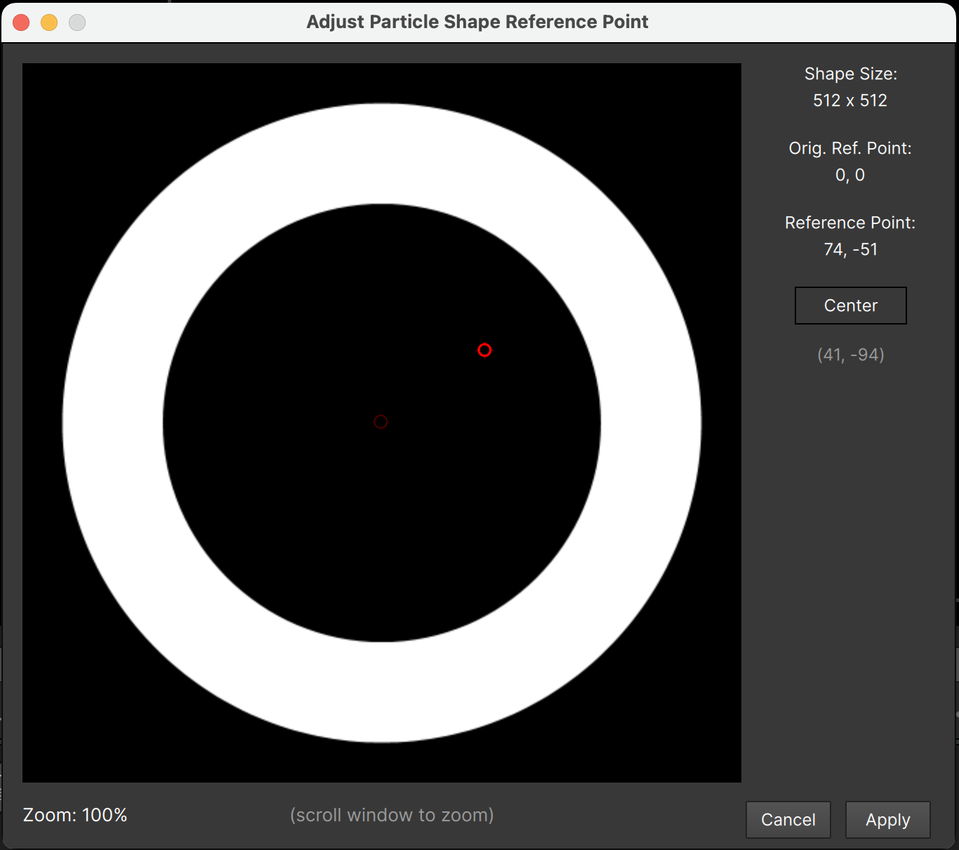
When you click to update the point position, you’ll see a faint indicator of the original position. Also the Stage will update as you make changes to the reference point, allowing you to see the results of any changes to the particles in your project.
Zoom the window by scrolling — zooming out is the only way to set the reference point farther away from the center.
You can set the reference point to the center of the image using the “Center” button.
One note about particle lines with an off-center reference point: lines always draw to the reference point, so will appear offset or “detached” from the sprite. The only way to avoid this is to reset the particle reference point back to the center.
Copying Particle Properties
There are often times when you’d like to copy properties from one particle node to another. It is not possible to do this for every parameter or property (although you can duplicate a particle node, or starting in v2026.5 link parameters together), there are three key properties that you CAN copy between particle nodes: the color gradient, the alpha gradient, and the particle image (sprite).
If you r-click on a particle node (or with the node selected use the “hamburger” menu in the controls view) you’ll see that there is a “Copy” command for each of these items:
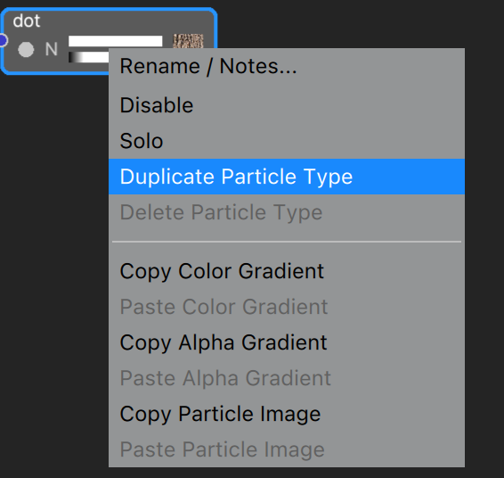
Once a color gradient, alpha gradient, or particle image has been “copied”, the corresponding “paste” menu item will be enabled.
(Note that these items are not copied to the clipboard.)
Although copying and pasting this way is extremely useful – for instance to make each particle node have the same color gradient – there is a faster way to accomplish this. You can alt-drag (option-drag on Mac) each of these items from one particle node and drop it onto any other particle node.
While dragging you’ll see a copy of the gradient or image, and it will dim when you’re not above a valid target node.
Note that alt-dragging an item in this way also “copies” it, so you’ll be able to use the corresponding “paste” command.
Parameter Linking
Sometimes you’ll want two different particle nodes to always have the exact same parameter value, for example the color gradient or sprite image. We’ve just seen that copying those from one particle node to another is not too difficult to do, but it’s not automatic.
With linked parameters it is automatic: change the parameter for one node and have it immediately update in any linked nodes!
To link parameters between nodes, select one of the nodes and r-click on the parameter name then choose “link”. A linked parameter shows in green. Here the “Color Gradient” parameter has been linked for the “star centers” particle node:
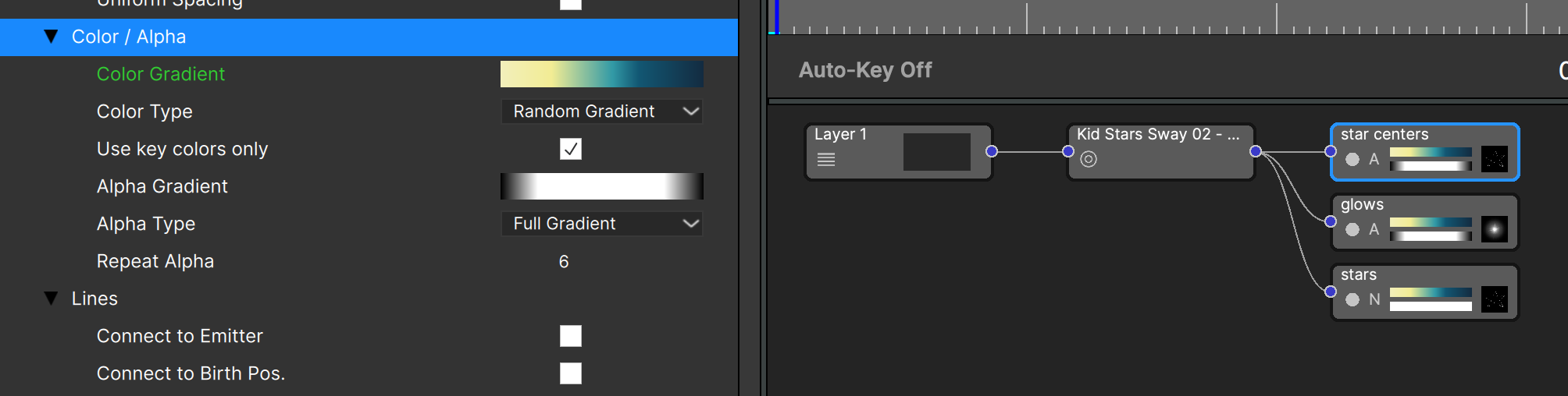
In order for linking to have any effect, more than one node must have the parameter linked, so here the process hase been repeated for the “glows” particle node:
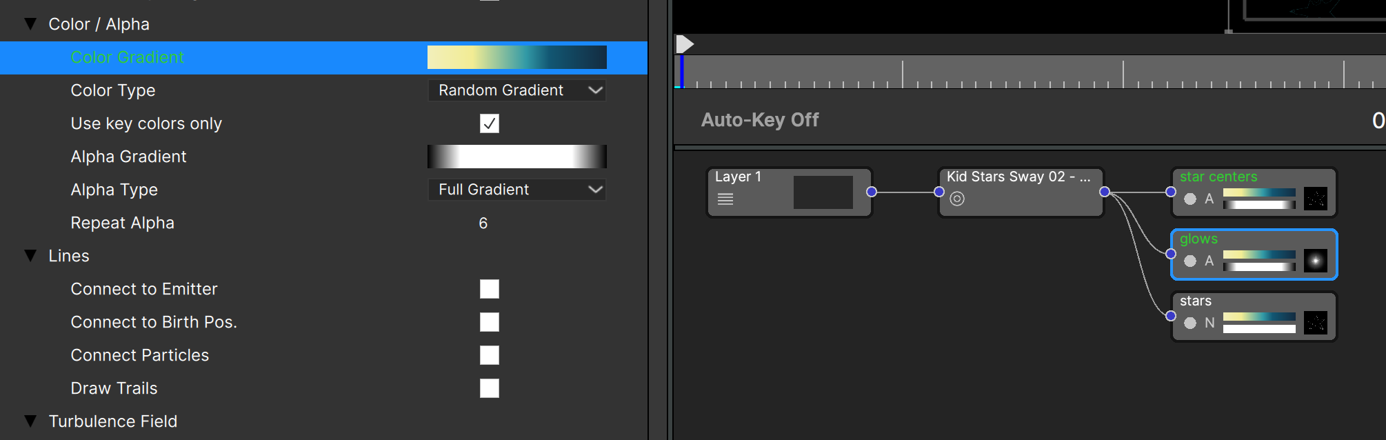
Notice that when a linked parameter is selected the node name turns green, showing which nodes are affected by this link.
Linking a parameter that is already linked in another node will copy the value from that other node.
Now that the Color Gradients are linked for these two nodes, changing the gradient for either of them will automatically update the other:
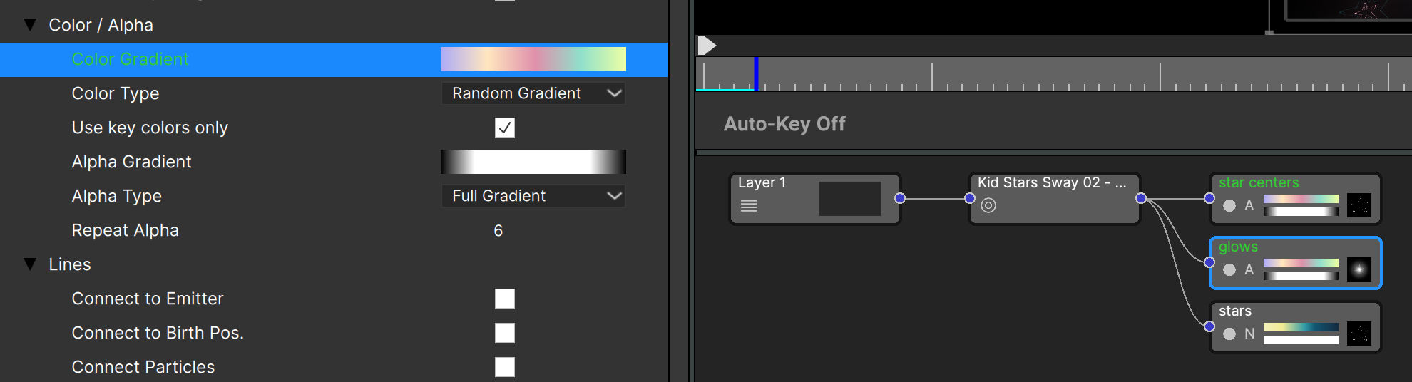
What if you wanted to share one color gradient for two nodes, but then want a different color gradient to be shared by two other nodes? Use the “Parameter Link Group” for this:
\
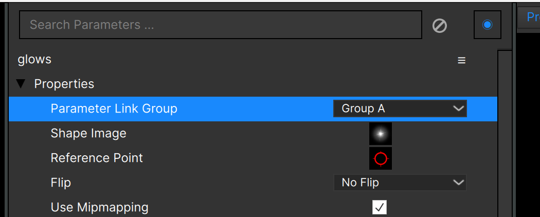
Note: the parameter link group applies to all parameters for a node.
Parameter Linking Helpers
Small-scale parameter linking can be very helpful and is probably the way this feature will typically be used. There is a more advanced usage case for particle linking though: when you want two different particle nodes to create particles that always appear together – all particles from one node exactly overlapping particles from another. (As if two different particles are “stacked” on top of each other.)
To make this happen you need to ensure that every parameter that controls the number of particles and their positions are exactly the same values for two different nodes.
Before parameter linking this would have been very difficult (although it’s been done in some presets), and even with linking it could be quite tedious to set up: which parameters are essential to link?
There is a one-click solution: Particle Type Cloning.
Right-click on a particle node and you’ll see three options related to linking:\
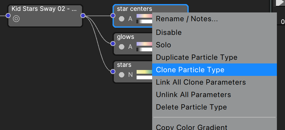
“Clone Particle Type” - This is the one-click solution for particle stacking. It duplicates the particle node and links all clone parameters (all parameters needed for stacking) in both nodes.
“Link All Clone Parameters” - Links all parameters needed for stacking in the current node only. Use this when you’ve already duplicated
“Unlink All Parameters” - Removes all links from this node. (Unlinks all parameters)
After cloning or linking all clone parameters you’ll see lots of green:
\
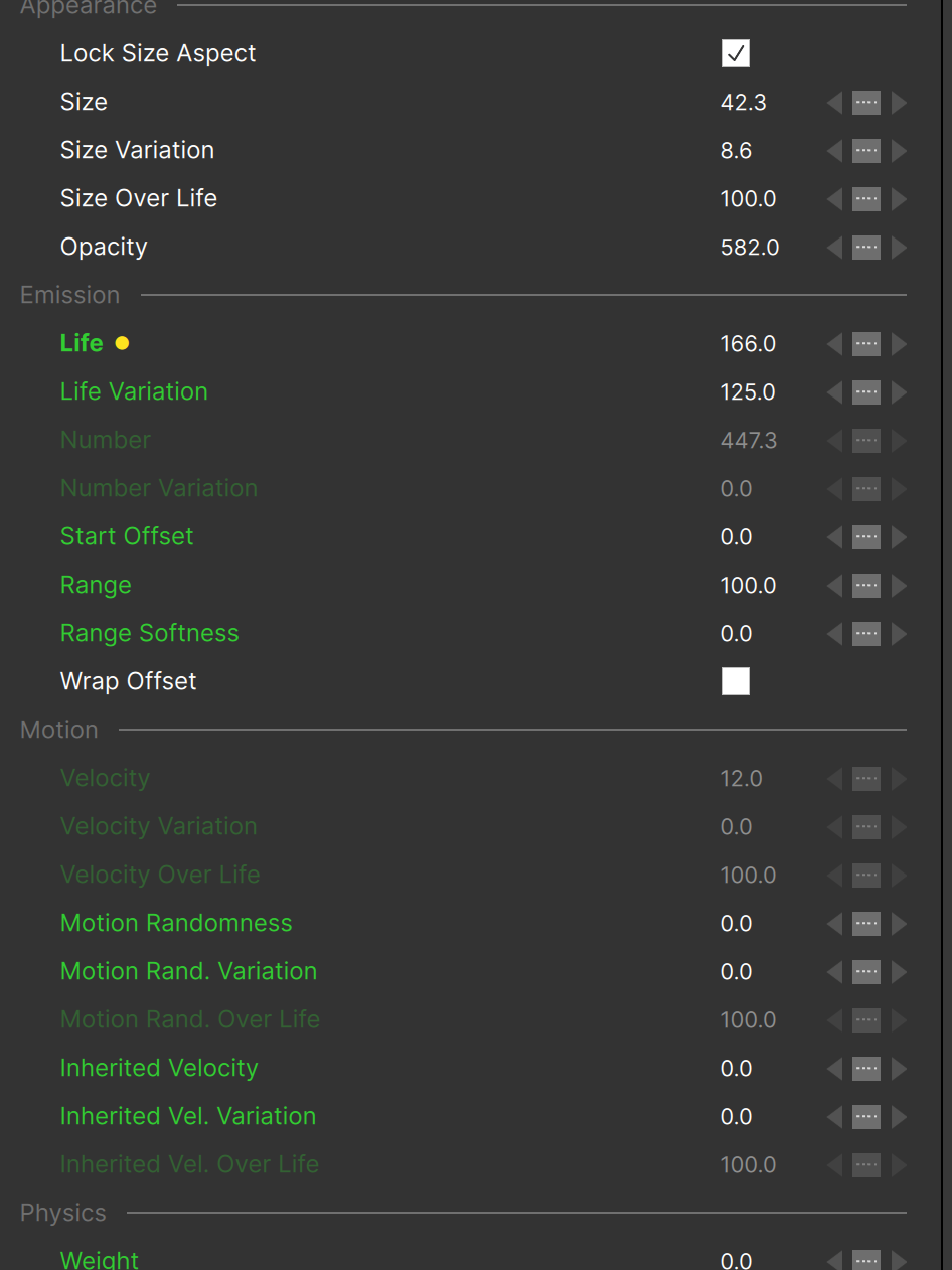
Note that when a linked parameter is also emphasized it will stay green but will show in bold and still have the golden yellow dot.
Emitter Shapes
In the emitter properties group you can select different “shapes” for the emitter, and depending on the shape chosen there are additional parameters that are revealed. The options in 2D projects are “Point”, “Line”, “Ellipse”, “Area” and “Circle”. In 3D projects they are expanded: “Point”, “Line”, “Ellipse”, “Plane”, “Circle”, “Box”, “Sphere”, “3D Model”, and “Ellipsoid”.
For “Point” emitters, the particles all emanate from a single point. This is the simplest shape for an emitter, and there are no additional parameters for it.
With “Line” emitters, the particles all emanate from a line or series of connected line segments. After switching the shape to “Line” you will see a line (if the HUD is enabled) from the emitter point to the mouse position. Clicking adds a new line point — double-click or press the ESC key to end the line. Line emitters have the following additional parameters:
- Emission In: particles will be emitted from one side of the line. Note that only when Emission Range is set below 360 degrees will you see this, and it will be most clear when the Emission Range is below 180 degrees.
- Emission Out: particles will be emitted from the other side of the line.
- Emit at Points: When checked the “Number Points” parameter becomes visible. Use this option to create a row of point emitters evenly spaced along the line (or line segments).
Note that on Mac Cmd-click will delete a line emitter point, and Option-click will allow you to add points to the line. On Windows Ctrl-click to delete a line point, and Alt-click to add them.
Set to “Ellipse”, the particles will be created along the ellipse. As with “Line” emitters, these additional parameters are available:
- Emission In: particles will be emitted toward the inside of the ellipse. Note that only when Emission Range is set below 360 degrees will you see this, and it will be most clear when the Emission Range is below 180 degrees.
- Emission Out: particles will be emitted toward the outside of the ellipse.
- Emit at Points: When checked the “Number Points” parameter becomes visible. Use this option to create evenly spaced point emitters along the ellipse.
In addition, “Ellipse” emitters have “X Radius” and “Y Radius” parameters which can be used to resize the ellipse.
Unlike the other shapes, “Area” emitters create particles throughout a rectangular area (not just along the outline). In 3D projects “Area” is called “Plane”, but it behaves the same. Area/Plane emitters add:
- Emit at Points: When checked the “Num Points X” and “Num Points Y” controls are revealed, allowing you to create a grid of point emitters.
- “Width” and “Height” parameters to control the dimensions of the rectangle.
A “Circle” emitter is a special case of “Ellipse”, in that only a single “Radius” parameter is added instead of “Radius X” and “Radius Y” — all other parameters for “Circle” emitters are the same as for “Ellipse” emitters.
“Box” and “Sphere” emitters are 3D analogs of the 2D “Area” and “Circle” shapes. Box emitters create particles throughout their volume (in the same way that “Area” emitters create points throughout the rectangle area), while “Sphere” emitters create particles along their surface (in the same way that “Circle” emitters create particles along the circumference).
“Ellipsoid” is the 3D version of “Ellipse”, and creates particles along the surface (just like Sphere).
Box emitters add a “Depth” parameter to complement “Height” and “Width”, and when “emit at points” is checked a “Number points Z” parameter is added.
One important note about emitter shapes other than “Point”: Line, Ellipse, Circle, Area, etc. emitters can emit more particles the “bigger” the shape. The “Scale Number with Shape” controls this:
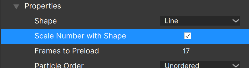
For instance, with this parameter checked a long line emitter will create many more particles than a short line emitter, a circle emitter with a large radius will create many more particles than a small radius, etc. The most extreme case of this is probably the “Area” emitters in 2D, and “Box” emitters in 3D — increasing the width and height of an area emitter so it fills the entire frame will most likely create many more particles than you intended, with the result of this being poor performance and greatly reduced responsiveness.
For this reason it’s a good idea to uncheck “Scale Number with Size” if you’ll be increasing the dimensions of a shaped emitter.
Alternately, reduce the “Number” value significantly before increasing the dimensions (line length, radius, width and/or height) of any shaped emitter, then increase it again slightly afterward if necessary. This will ensure that performance and responsiveness stays optimal.
If you change an emitter shape and you don’t see the stage update right away, you may want to immediately uncheck “Scale Number with Size” or decrease the “Number” parameter to something very small — you don’t have to wait until the stage updates.
3D Models
When the “3D Model” emitter shape is selected, a file dialog immediately shows to allow you to choose the 3D model file to use for the emitter. Both C4D and OBJ file formats are supported by Particle Illusion.
After selecting a model file, the parameters specific to 3D models are displayed:

“Model File”: shows the filename of the current 3D model. Click to select a new model. (The tooltip for this parameter shows the full path to the current file.)
“Emit From”: Select what part of the model to use for emission: “Vertices”, “Edges”, “Surface”, or “Normal”
“Threshold Angle”: Only visible when emitting from “Vertices” or “Edges”. This sets the threshold angle for emission. For instance when set to “Edges” using a cylinder model, a threshold angle of less than 12 degrees will result in emission from most (or all edges):

While a threshold angle of more than 12 but less than 90 degrees will result in emission from the sharp edges only (the ends of the cylinder):

“Subdivide Large Polys”. This parameter is visible only with “Surface” emission, and is used to help distribute particle creation more evenly when your model contains a mix of large and small faces. When unchecked the smaller faces will have a higher particle density.
“Model Scale”: Scales the 3D model uniformly in all dimensions. (Note that upon import the 3D model scale is normalized to fit the frame – there is no way to turn that off. “Model Scale” is applied on top of that internal normalization.
“Model Scale X/Y/Z”: Used to scale the model along a specific axis.
“Use Model Color for Tint”: When checked, the color information stored in the model will be used instead of the “Tint Color”, and will be mixed with the selected wireframe color using the “Tint Strength” value.
“Show Wireframe”: Displays a wireframe of the model.
When “Show Wireframe” is checked, wireframe properties are shown:

Use these to set the wireframe opacity, color, and line thickness. The wireframe is very similar to the particle “lines” feature, except that Emitter “Tint Color” does not affect the wireframe.
Although the Wireframe Thickness value can be set to any value between 0.0 and 20.0, you may find that only specific values make a visible difference. This is entirely based on your hardware and or graphics driver — for instance a value of 0.5 might look exactly like a value of 0.9, then 1.0 will increase the visible thickness. Integer values should always work (we haven’t found a case yet where they don’t), so it’s probably best to stick to whole numbers.
Model Colors/Textures
When the 3D model uses colors, we’ve already seen that “Use Model Color for Tint” allows you to use those colors with “Tint Strength”.
If the model contains textures, “Use Model Color for Tint” pulls the colors from the texture instead of the model color. This can produce some complex effects:
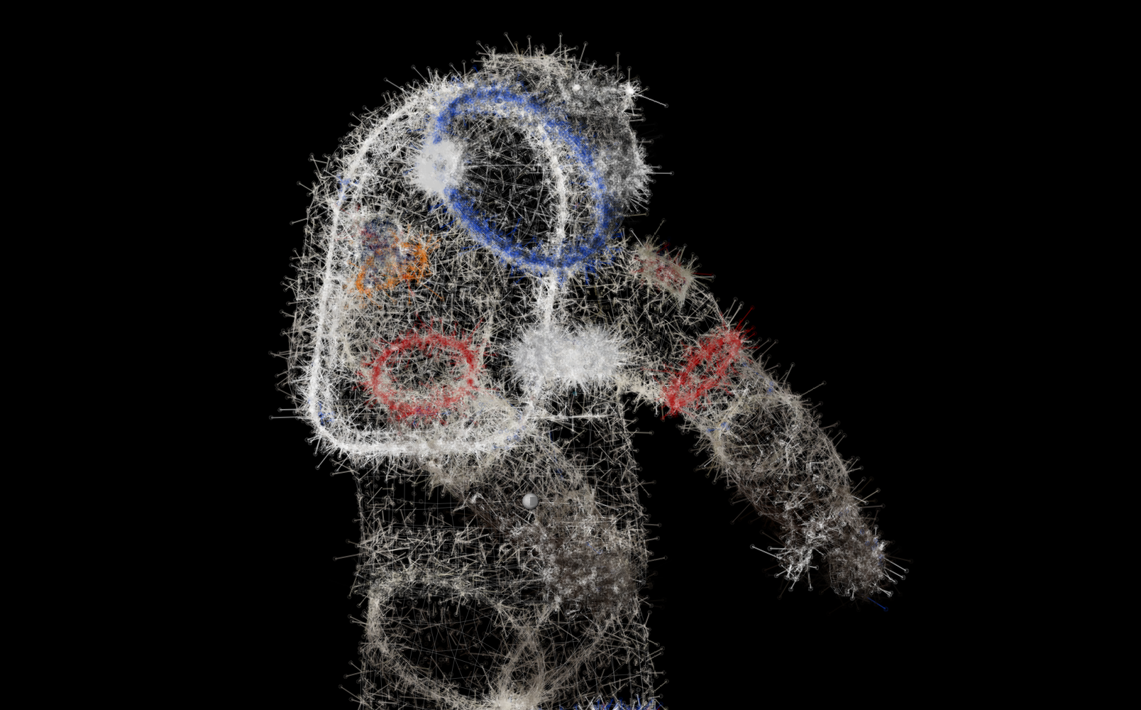
Note that C4D models contain texture data, but OBJ models have textures as separate files. The texture file needs to reside in the same folder as the OBJ model. Also, when adding an emitter (or saving a scene) that contains an OBJ 3D Model, the model is copied to the PI3DModels folder, but the texture file is not – it must be copied manually.
Super Emitters
Remember that a “super emitter” is a special type of emitter in Particle Illusion that does not create particles directly, but creates other emitters (free emitters) which in turn create the particles.

With a free emitter node selected in the Nodes View (as shown above), the Controls View will display something like this:
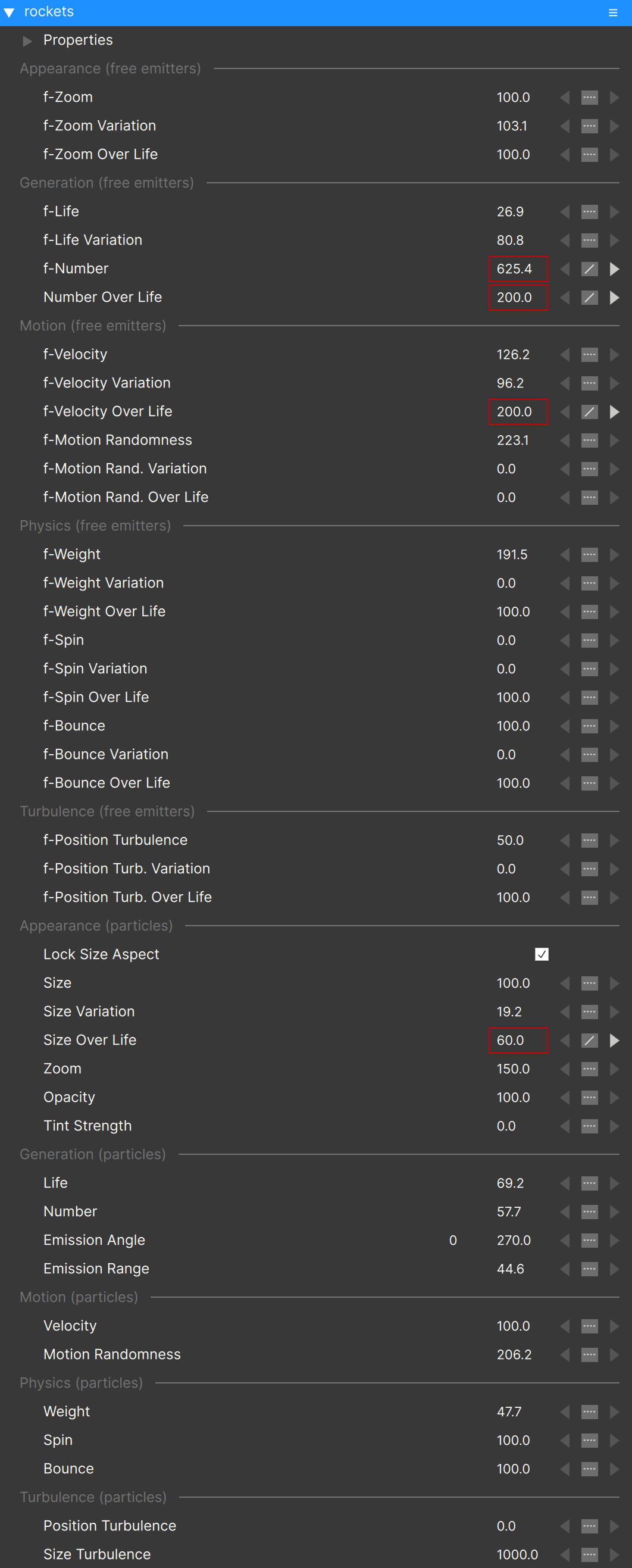
The “f-” parameters such as “f-Life”, “f-Number”, “f-Velocity”, etc. are applied to the free emitters themselves and do not control particles. (This is further indicated by the section titles, which will note either “free emitters” or “particles” as a reminder of what these parameters control.)
For example, to create more free emitters, increase the “f-Number” value. To make the free emitters move faster, it is “f-Velocity” that must be adjusted.
You’ll notice that there is no “f-Size” parameter. This is because free emitters are not visible, and therefore do not need a “size” control.
Similar to the parameters for particle types which were discussed earlier, there are also “Variation” and “Over Life” controls for the “f-” parameters.
Starting In the “Appearance (particles)” section you will see what looks like the same set of parameters that were visible at both the emitter and particle type levels: “Life”, “Number”, “Size”, etc. These are the scale factors for the corresponding controls in all of the particle types that this Free Emitter Type contains — they control the particles.
This means that for a Super Emitter there are two different levels of scale factors that are applied to the particle type parameters.
This may seem overly complex and a bit difficult to grasp when reading it, and when you’re looking at an emitter that contains only a single particle type, it may be overkill. The advantage of this system of a hierarchy of controls becomes apparent when dealing with emitters that have several different particle types though.
Note that parameter de-emphasis can also help to understand the difference between “f-Velocity” and “Velocity”. Set “f-Velocity” to 0 and you’ll see the parent emitter’s “Velocity” parameter de-emphasize. Set the free emitter “Velocity” parameter to 0 and you’ll see the particle type “Velocity” and “Velocity Variation” parameters de-emphasize.
Animating Parameters
Most parameters that can be animated — by manually creating keys to change values over time — displays the keyframe controls to the right of the parameter value in the Controls View:

Note that any parameter that is animated (contains more than one key value) has its value outlined by a red rectangle. The left and right arrows are the key navigation buttons, and clicking them jumps the current time indicator (CTI) to the frame of the appropriate key. (Except when an “over life” parameter is selected.)
The interpolation control is between the two key navigation buttons, and is used to switch the interpolation type of the current key. Note that if the CTI is not at a keyframe, the interpolation type will not display (will show as an empty box).
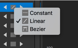
Interpolation Type Choices:
Linear: The value changes at this key occur linearly, along a straight line.
Bezier: The value changes along a smooth curve that is adjusted in the Graph View using the control point “handles”.
Constant: Setting a “constant” value removes all keys from this parameter.
To adjust keys in the Graph View, you can just click and drag them. You can also change the parameter value itself in the Controls View. If the CTI is at a keyframe when you change that value, that key will be adjusted. If the CTI is not already at a keyframe and the graph already contains a key, a new key will be created. (If you adjust the value for a “Constant” parameter, the value will change but no key will be created.) More in the “Working with Data Keys” section below.
There is another way to create keys to animate a parameter: using the animation controls. These are found just under the mini-timeline, above the Graph View on the left:
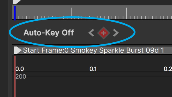
The buttons with the left and right arrows are key navigation controls, and they have the same effect as the buttons to the right of the parameter value in the Controls View: they move the CTI to the next or previous data key (if they exist).
The button with the “+” sign adds a key at the current frame for the current parameter. Note that this works even when the parameter interpolation is set to “Constant”.
When at a frame with an existing key, this button changes from “+” to “-”, and can be used to remove (delete) the key.
The “Auto-Key” button is a toggle; when turned on any parameter changes will create keys. Since there are other ways of creating keys for most parameters, this may not be a button you’ll use often.
When a Position or Angle parameter is selected, the graph view updates with an “XYZ” picker in the upper left corner:
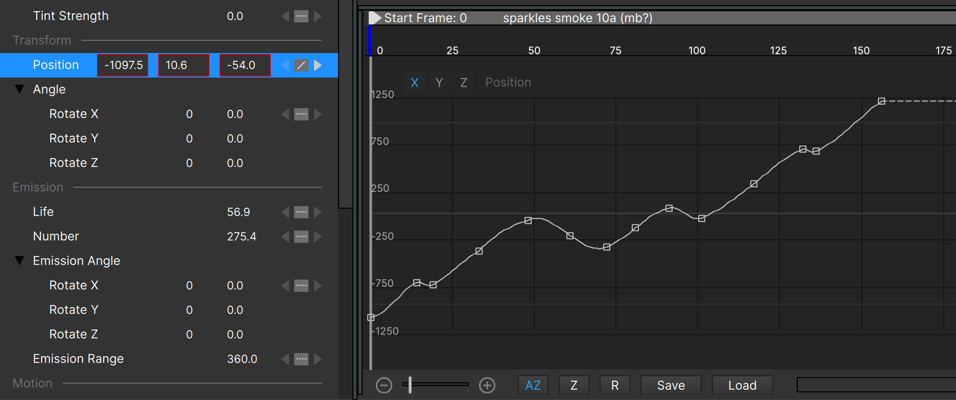
Both Position and Angle parameters contain three components, but only one is visible in the graph at a time. This XYZ picker lets you choose between them.
Animating Emitter Position
All parameters including position can be animated using the control view and graph view, but there is an easier way of animating position parameter: using the Stage.
Emitter (and other object) position changes, for animation or not, can be made in the Stage by clicking and dragging the emitter. (This is usually much easier than manually creating position keys by entering specific values in the Controls View.)
To animate the emitter position in the Stage:
- Click on the emitter in the Stage and drag it to its starting position.
- Toggle the “Animate” button on, click the “Add Key” button, or select “Linear” as interpolation type in the Controls View.
- Jump the current time indicator (CTI) forward some number of frames
- Drag the emitter in the Stage. You should see the emitter motion path in the Stage now:
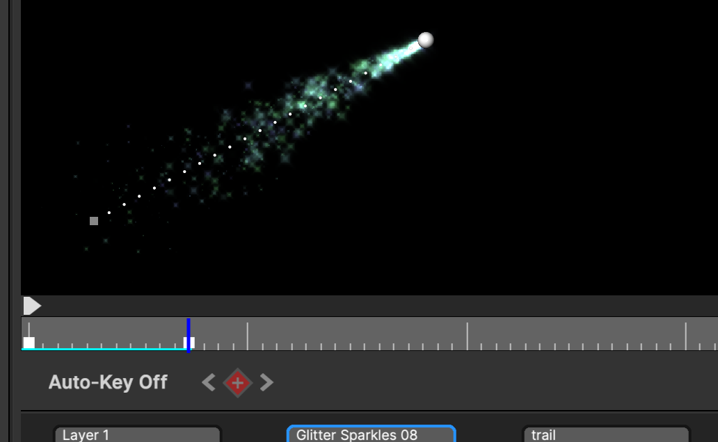
You can now continue moving the CTI and dragging the emitter to create new position keys as needed. (Once a position key is created, new keys are created automatically.)
To create position keys that are between two existing keys, just move the CTI between those keys and drag the emitter — a new key is created regardless of the stage of the Animate button.
Note that you can click and drag position keys directly in the Stage, similar to the way that you can do this in the Graph View for other parameters.
To change a position key from “Linear” to “Bezier”, Alt/Option click on the key in the Stage, or use the interpolation control to the right of the Position XY values in the Controls View — just as you would for any other parameter.
Note that the emitter position at each frame is indicated by small dots:
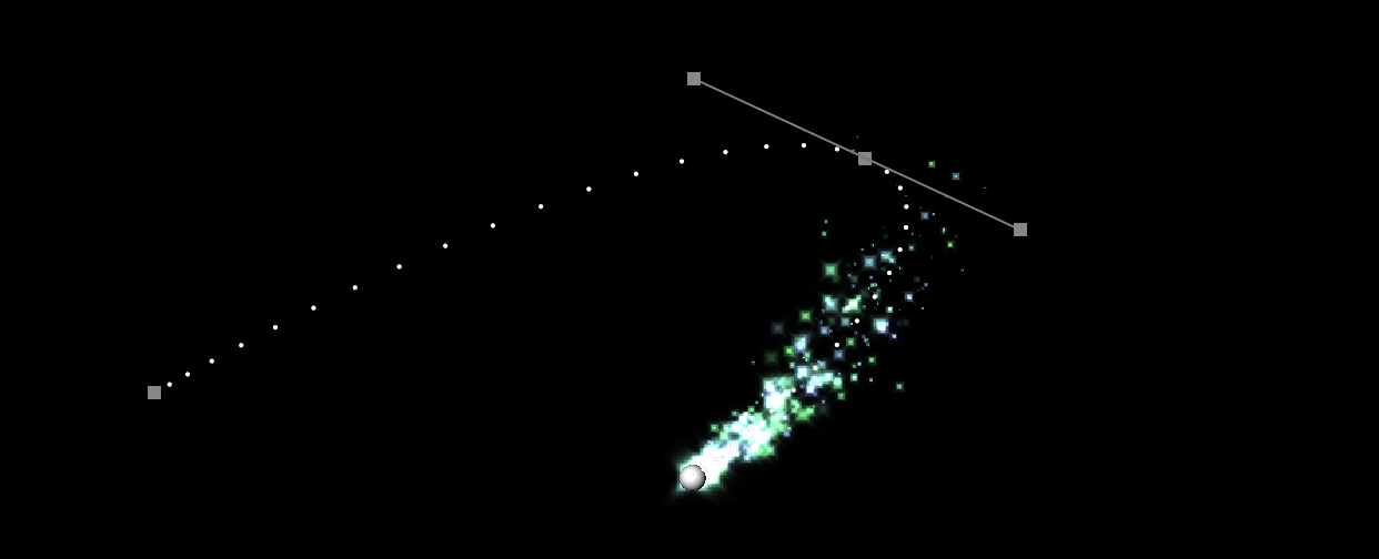
(Note that you can set the size, color, and opacity of these elements in the HUD page of the Preferences dialog.)
You can “disconnect” Bezier handles by Alt/Option-clicking on the handle itself. Disconnected handles show darker than connected ones, and can be moved independently:
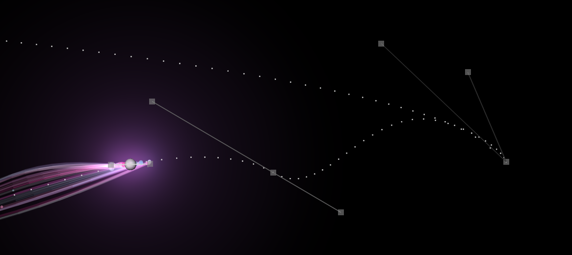
Note the difference between the connected (left) and disconnected (right) Bezier handles.
To connect the handles again, Alt/Option-click on either handle again, or change the key to “Linear” then back to “Bezier”.
Position Path Presets
It was mentioned in another section but is worth stating again here: you can also load Position Path Presets into any position parameter. Select the Position parameter and click the “Load” button below the graph to bring up the preset dialog:
More about position path presets [can be found here](#position_path_presets).
Equalize Path Timing
As you create an animation path by moving the emitter in the Stage, you may notice that the time between each position key isn’t consistent – the visual spacing of the emitter position (shown by the dots) is not equal – so the emitter moves more slowly at times, and more quickly at others.
Often times this may be exactly what you want, but maybe you’ve scaled a position path preset and adjusted the start and end positions to move the emitter out of frame, and the emitter motion now varies greatly, something like this:
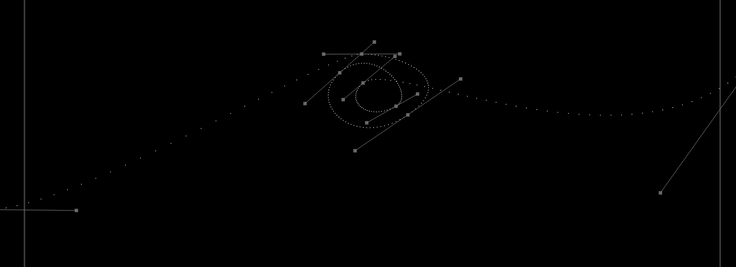
To get a consistent emitter motion speed throughout the position animation, r-click on the Position parameter and select “Equalize Path Timing”:
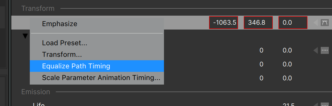
Which results in a much more consistent motion timing:
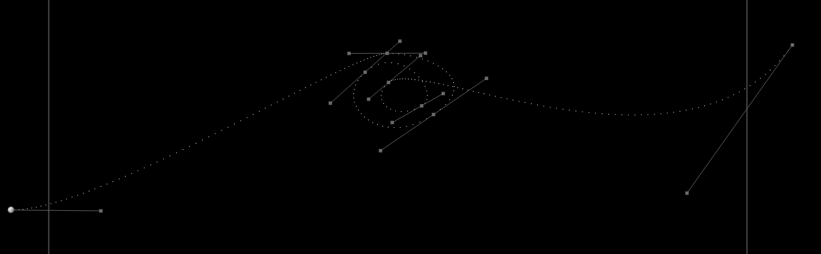
Note that when Bezier curves are involved you may still need to adjust the timing of some position keys, which is easily done using the mini timeline.
Position and Angle in 3D
When discussing creating position data keys above, we mentioned that you can just click and drag the emitter to position it.
There is another way to position, rotate, and in some cases even scale the emitter in the stage. Instead of clicking and dragging the emitter, click and release (to select it). This will display the 3D widget (or “interactor”):

The widget allows you to drag the emitter along a specific axis, while also letting you drag it freely in the current view plane.
When you roll over an axis arrow or plane square, it will highlight in yellow – click and drag to move the emitter along that axis or plane.
There are three modes for the widgets/interactors which are indicated by the icons above the stage (see image above): translate, rotate, and scale. You can switch between the modes using the hotkeys W, E, and R (as shown in the tooltips for each mode icon).
Note that the Scale widget will only have an effect in certain cases: it’s possible to use the scale widget to resize a Box emitter in any specific direction for instance, but the scale widget does nothing for a point emitter.
World vs. Object Coordinates
Once an object is rotated, you can use the translate widget to move it along its own coordinate system, or instead along the world (screen) coordinates, depending on the state of the “World Coords” button. With “World Coords” off, the widget is aligned to the object’s rotated coords:

Remember that when widgets are not displayed, you can always click and drag an emitter to position it in the current view – widgets just give you more control when you need it.
Working with Data Keys
We mentioned already that it’s possible to click and drag a data key in the Graph View, and that you can change a data key’s value using the Controls View. There are a few other features that make working with data keys easier:
- Multi-selecting data keys. You can shift-click on keys in the graph view to select multiples, or click and drag to create a selection rectangle that will select multiple keys. All selected keys can be dragged as a group.
- Deleting data keys. Use your keyboard “delete” key to delete all selected keys.
When a data key is set to “Bezier” interpolation, you can drag the control handles to change the curve. In addition, you can:
- On Mac: Option-drag a bezier handle disconnects the two handles and lets them move independently. Option-drag on one of the disconnected handles to reconnect them.
- On Windows: Alt-drag a bezier handle disconnects the two handles and lets them move independently. Alt-drag on one of the disconnected handles to reconnect them.
Note that disconnected Bezier handles in the Graph View show in color:
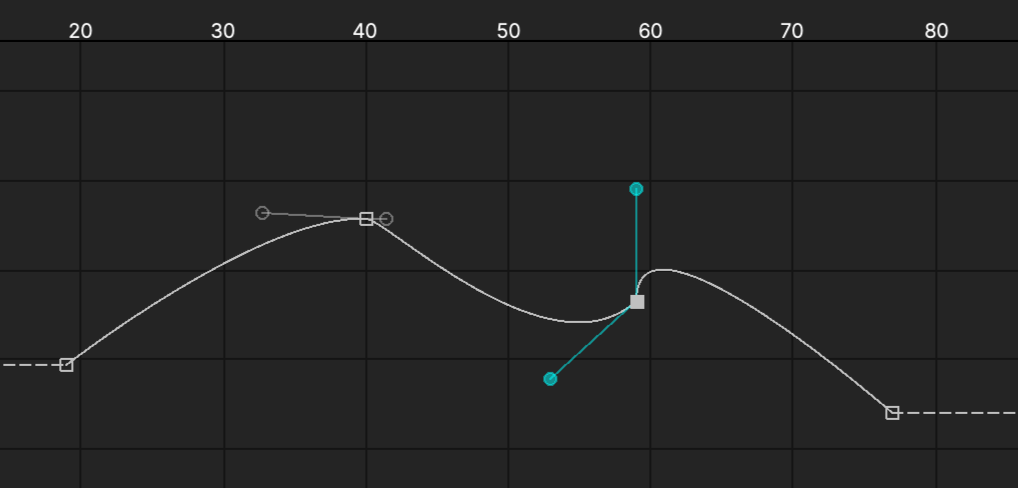
Using the Playback Controls
The playback controls appear above the Graph View and below the Stage:
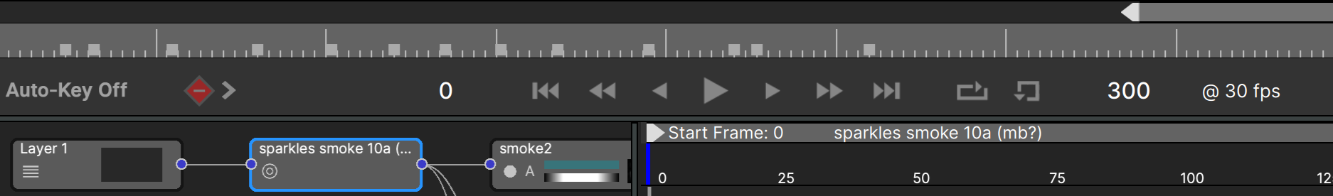
These allow you to toggle playback, move one frame forward/back, move 10 frames forward/back, or jump to the start frame (frame 0) or end frame. The spacebar is a keyboard shortcut for the play button.
There is also a “looping” control that should be self-explanatory, and at the far right end an “Auto-Rewind” button. When this is enabled, stopping playback will jump the CTI back to frame at which playback started – otherwise the CTI just stays at its current position when playback stops.
The current frame number is shown to the left of the playback controls, and the length of the project in frames is shown to the right.
Note that you can click the number of frames as a shortcut to open up the Project Settings dialog.
The Mini Timeline
The area just above the playback buttons — where the blue frame indicator line shows — is called the “Mini Timeline”. You can click anywhere in the Mini Timeline to jump the current time indicator (CTI) to that frame.
This is also where keys are shown for the selected parameter — if you want to change the position of any keyframes you can do that in the Mini Timeline. Doing it here removes the risk that you might unintentionally change a keys value when trying to move it in the Graph View.
In and Out Points
Just above the Mini Timeline are the trim controls for setting the In and Out points. Drag them to set the playback range, or double-click between them to clear both of them and reset to the full play range.
For those who want more precise control over the In/Out controls, you can “nudge” these one frame at a time: hover the mouse cursor over the control, then use the L/R arrow keys to nudge. (Once the cursor moves off the In/Out marker, the arrow keys stop working.)
You can click in the play range (the area between In and Out) and drag to reposition In and Out together.
To jump the Out point in 1-second steps, position the cursor over the play range and use the mouse wheel or scroll gesture.
Note that start/end frame controls have dual usage: click the start frame button once to move to frame 0, then click it again to move to the “in” frame. Similarly the end frame control jumps to the last frame in the project, then to the “out” frame.
Jump by Five
When working in the mini timeline, it’s possible to jump the frame number to the nearest multiple of 5. When dragging the CTI, the In point, or Out point, just hold the Shift key.
Cache Indicator
You will have noticed that in the mini timeline there is a cyan line that draws from frame 1 to the CTI. This is the cache indicator. Particle Illusion will cache particle calculations which allows for better performance when scrubbing the timeline (under many circumstances). Note that it is not an image cache, so for projects with a large number of particles you may still not get smooth scrubbing.
If you ever notice something strange happening during playback — particles that glitch or jump for instance — you should reset the cache. An easy way to do this is to just select any parameter value and change it slightly, or even just click on it as if you were to type a new value but just hit Enter/Return to keep the same value. Once the cache recalculates the glitch should no longer occur.
Emitter Start Frame
Below the playback controls is the Start Frame slider for the selected emitter:
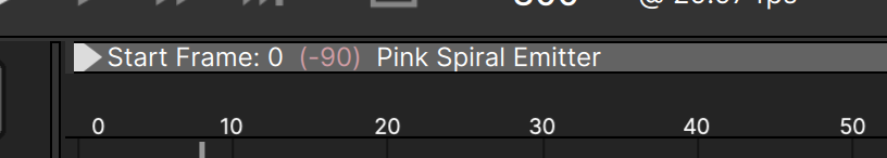
By default added emitters are placed so that they start at the current frame. To make the emitter start at a different frame, just slide the head of this Start Frame slider by clicking and dragging it. Note that all data keys contained in this emitter will move with the slider — this is most important for emitters that have significant animation or turn off, such as explosion emitters.
Tip: the Start Frame also responds to the Shift key modifier to jump by five frames.
Note that if for some reason you don’t want the data keys to move with the slider you can CMD+click and drag on the slider head (on Windows CTRL+click and drag). This could be useful if, for instance, you want an explosion emitter to create particles for a bit longer before turning off. Instead of moving all of the “number” data keys to a later time (to the right) — and there could be several different “number” parameters where you’d have to do this — you can instead CMD-drag the Start Frame slider to an earlier time (to the left).
The Start Frame slider shows a pale red negative number for some emitters (see image above). This is a reminder that the emitter has a non-zero value for the “Frames to Preload” parameter. Clicking the number on the Start Frame slider will highlight the parameter in the Controls View.
Emitter Libraries
Particle Illusion is preset driven, and there are well over 2500 particle emitters in the various emitter libraries. Only three libraries — the locked “Sampler” library, the locked library for this release (for instance “Emitters_2026.0”) and the editable “Custom” library — are installed with Particle Illusion. To get the additional libraries use the link provided in the “Help” menu:
You’ll need to restart Particle Illusion after installing those libraries to make them available.
If you see a red warning icon above the library browser…
![]()
…this is another indication that you don’t have all of the emitter libraries. Hover the mouse cursor over this icon for more information.
The concept of libraries is not so important in Particle Illusion because of the search function, but libraries do provide some level of organization. The important thing to know is that the legacy emitters have been grouped into themed libraries, so that most smoke emitters are in the “Smoke” library, explosions are in “Explosions”, etc. (The newest emitters are released in versioned libraries: “Emitters_2021.5” for instance.)
This is only important if you’re manually browsing the libraries, but with so many emitters to look at the only realistic way to browse is to first use the emitter search function.
Library Scenes
Starting with Particle Illusion 2022, libraries can now contain “Scenes” along with emitters. Scenes are similar to emitters in a library in that they both are a type of preset, both have thumbnail images, and both are added to the project in the same way. There are significant differences though:
- Scenes have a “+” symbol before their name
- Scenes only show their thumbnail image in the preview — it is not a live preview
- Scenes can contain multiple emitters, forces, and deflectors. (It is this complexity that requires the removal of the live preview)
- Scenes preserve position data, so are always added at absolute positions (you can’t click to add a Scene at a different position in the Stage)
Emitter Search
The emitter search can really help you reduce the number of emitters that you need to browse, and is the best way to quickly find what you’re looking for without a huge amount of scrolling.
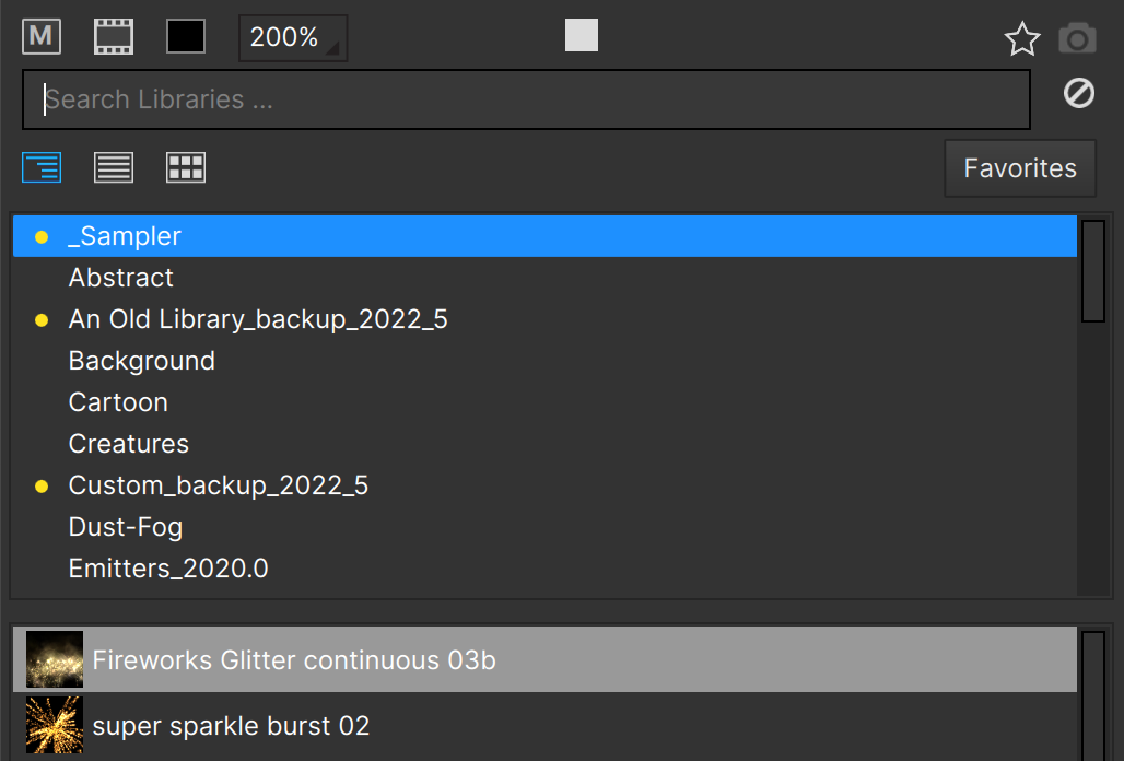
To search the emitter libraries, just start typing in the Search box below the preview.
The emitter search works over emitter names and on the tags saved with each emitter, and optionally on the folder/group names (which are only visible in List View).
Note that search works on Scenes as well as emitters.
In the Preferences for Particle Illusion there are a few options related to emitter searching:
- Search Folder Names: the folders in each emitter library are included in search results. When this option is checked all emitters in that folder will be included in the results if the search term is in the folder name. (This is not usually desired so is unchecked by default.)
- Search Tags: If you want to search only on emitter names you can uncheck this option. (It is checked by default as there are many emitters with names that are not descriptive.)
- Display Tags in emitter library: when checked, each emitter’s tags will display after its name in Library View. (The tags will not show in List or Grid views)
Here’s a list of all emitter search tags used in the emitter libraries:
Abstract - AlphaFromLayer - Background - Cartoon, Toon - Clouds - Creatures - Disintegrate, Disintegration - Dust - Explosion, Burst, Pyro - Fire, Flames, Pyro - Fireworks, Pyro - Geometry, Shapes - Magic - Nature - Rain - Sci-Fi - Smoke - Snow - Space - Sparkles - Sparks - Teleport, Transport - Text - Texture - Trail - UI, HUD, Interface - Water - Distortion
Bright - Colorful - Dark - Extreme - Falling - Fast - Fiery - Flowing, Drifting - Geometric - Glowing - Lines - Miscellaneous,Misc - Natural - Puff - Rising - Simple - Slow - Smoky - Smooth - Sparkly - Turbulent, Turbulence
RegularEmitter - SuperEmitter
Black - Blue - Brown - Green - Grey, Gray - Orange - Pink - Purple, Violet - Red - White - Yellow, Gold
v2020.0 - v2020.5 - v2021.0 - v2021.5 - v2022.0 - v2022.5 - v2023.0 - v2023.5 - v2024.0 - v2024.5 - v2025.0 - v2025.5 - v2026.0
Scene - Fluids - Mask/Masking
Knowing these can help you search more effectively.
Note that tags can be combined, so searching for “sparkles red” will return all emitters tagged with both “red” and “sparkles”.
Also note that new emitters are included with most major releases. For instance, the new emitters in the Continuum 2026 release are in the library “Emitters_2026.0” — you can easily find these using the search tag “2026.0”.
Tip: It’s easy to isolate the library Scenes using search: just search on the “Scene” tag.
Locked vs. Unlocked Libraries
All libraries installed by either Particle Illusion or the Additional Emitter Libraries installer will be “locked” and can’t be edited with one exception: the “Custom” library. This is provided as a place to store your own emitters — it contains just a single very basic (not useful) emitter because emitter libraries can’t be empty.
The locked vs. unlocked status of an emitter library is determined by where the library file resides: there is one folder for “locked” libraries, and one folder for editable libraries. You can manually move or copy emitters from one folder to another as necessary. It is recommended that the emitter libraries released by Boris FX remain locked.
Locked emitter libraries are found in the following folder:
Mac:/Library/Application Support/BorisFX/EmitterLibraries
Windows: C:\ProgramData\BorisFX\EmitterLibraries
The unlocked (editable) emitter libraries are found in the following folder:
Mac: /Library/Application Support/BorisFX/UserEmitterLibraries
Windows: C:\ProgramData\BorisFX\UserEmitterLibraries
Note that if you used (or are still using) the legacy version of particleIllusion 3.0 and created emitter libraries with it, those libraries can still be used in Particle Illusion. There is no “Load Library” command, so in order for Particle Illusion to find your emitter libraries you’ll need to copy them to one of those folders.
The more emitter libraries that are in those folders, the longer PI will take to load all of them, so you may want to be selective when you’re adding emitter libraries. Note that if you just copy all of the legacy pI3 emitter libraries for use in PI, you will have over 2500 duplicates — we curated the legacy pI3 libraries to create the PI libraries.
Adding an Emitter to a Library
Any emitter in your project can be added to one of the editable libraries. To do this, click the “hamburger” menu button to the right of the emitter in the controls view (or r-click the emitter node), then select “Save to Emitter Library…”
The “Save to Emitter Library” dialog then opens….
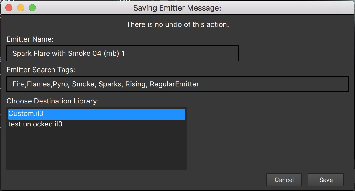
…and lets you rename the emitter, edit the emitter tags, and then choose the destination library (if more than one unlocked library exists).
As the dialog message indicates, there is no undo of adding an emitter to a library.
Adding a Scene to a Library
When you add an emitter to the library since it’s a single object you do it from the emitter’s “hamburger”/context menu. Since a scene contains everything in your project, you use the “File” menu to add it to a library:
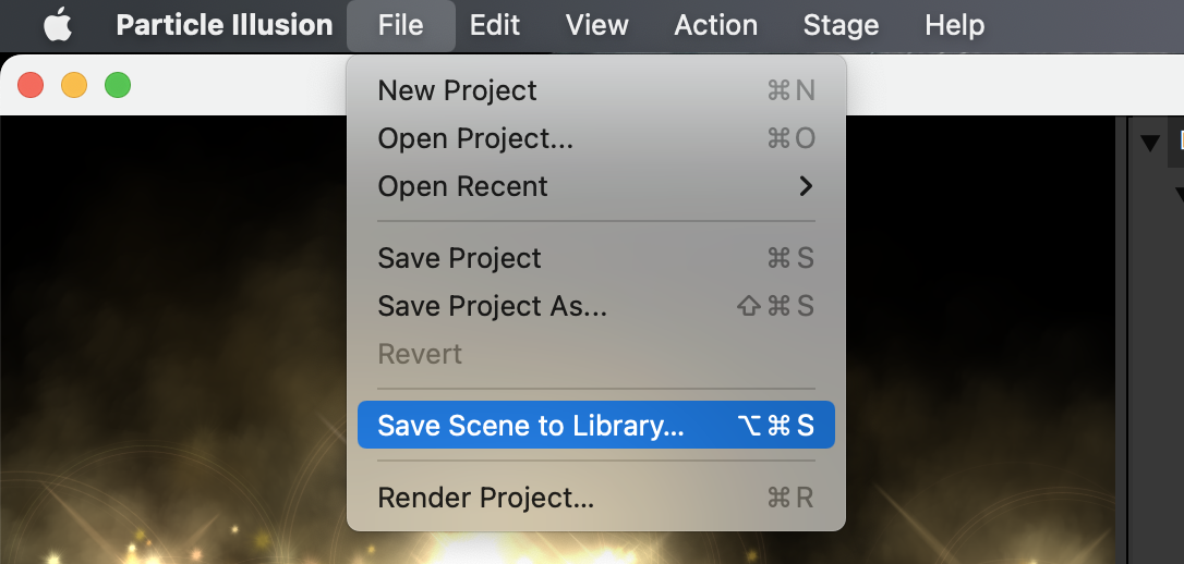
Think of it as being similar to saving the project, but you’re saving it in the library instead of a project file.
Note that a Scene is not exactly the same as a project, as the following information that is saved in a project is NOT saved in library Scenes:
- Motion Blur settings
- Stage size (resolution)
- Camera data
- Layer data (position, rotation, etc.)
- Node layout
When you add a scene to a library, the exact contents of the Stage are used for the Scene thumbnail (cropped to a square), so you should make sure you move the CTI to a frame that is representative of the Scene. (Unlike with Library Emitters, It’s not possible to update the Scene thumbnail after it is added.)
Deleting Emitters/Scenes from a Library
To delete an emitter or Scene from a library, select the emitter/Scene then hit the
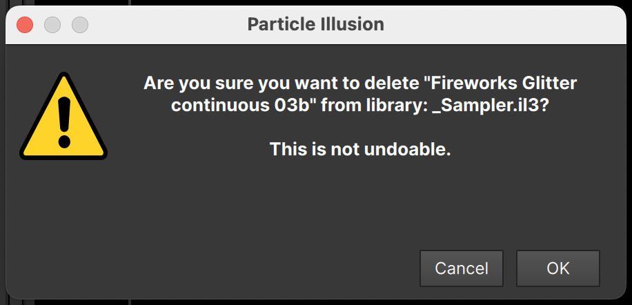
If the selected emitter/Scene is in a locked library, you will see an error message instead.
Emitter “Hamburger Menu”
The “hamburger menu” is accessed using the icon to the right of the emitter name in the controls view:
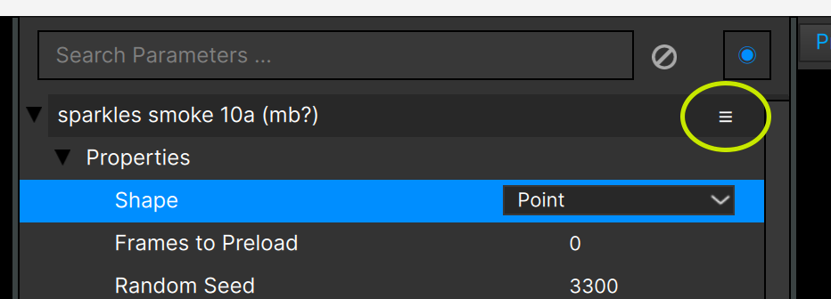
Click the icon to display the menu:

Besides saving an emitter to a library, using the emitter “hamburger menu” you can also:
- Disable an emitter, which removes it from displaying and rendering.
- Solo the emitter
- Delete the emitter
- Duplicate it, making an exact copy of it
- Move it Up or Down in the layer (if more than one emitter exists) to change the render order in 2D projects only (Does not change render order in 3D projects)
Note that the Hamburger Menu is exactly the same as the context menu shown when R-clicking a node in the Nodes View. With it you can also:
- Replace with Library Emitter
If you’ve animated your emitter’s position and then want to switch to a different emitter, select the new emitter in the library, then use the “Replace with Library Emitter” menu item. (Only the emitter position animation will be retained – any other parameters will be replaced with what is contained in the library emitter)
- Scale Emitter Animation Timing (which is discussed [in this section](#scale_animation_timing))
- Stop Emission when Motion Ends
<div id=“stop_emission_when_motion_ends>
If your emitter has an animated position (after applying a position path preset for instance), you may want the emitter to stop creating particles once it reaches the end of the animation. Use “Stop Emission when Motion Ends” and you’ll see the Number graph displayed, and some keyframes will have been added for you automatically to achieve this.
Note that this is an animation helper only – if you then change the timing of the position animation, or change the animation so it ends at a different frame, you’ll need to apply this function again.
- Import and export position data
Allows you to import data that has been exported from Mocha or Synth Eyes. [More details here](#import_position_data).
Renaming Library Emitters/Scenes
You can easily rename an emitter/Scene or modify its tags in any unlocked library. Simply select the emitter/Scene then hit the Enter/Return key, and the rename dialog will appear.
You cannot modify emitters or Scenes that are in locked libraries. See the section on Locked vs. Unlocked Libraries above.
Adding/Removing Particle Types and Free Emitter Types
We’ve discussed all of the parameter changes you can make to a particle type (and to a free emitter type for super emitters), but we have not talked about how you can create a new particle type, or delete an existing one from an emitter.
Once a regular emitter is added to your project, you can create a new “basic” particle type using the “Add New Particle Type” option in the hamburger/context menu:
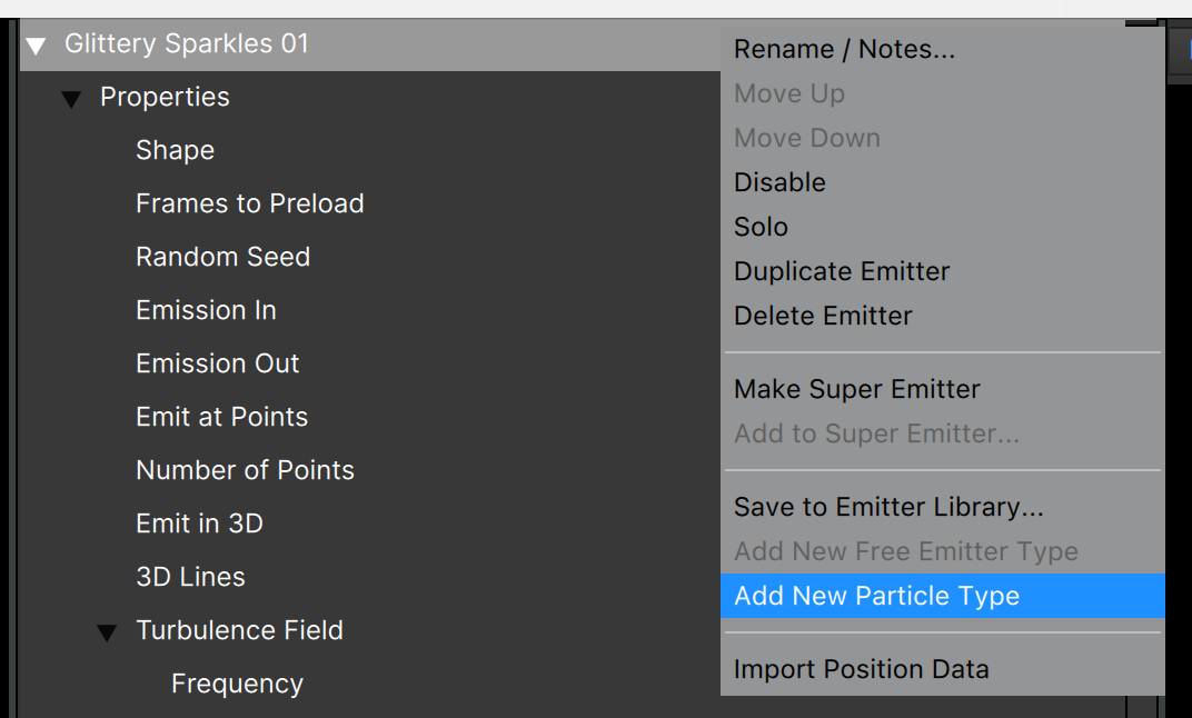
This will create a generic particle type using the first particle shape image from this current emitter, default parameters, and solid white for color gradient and alpha. You’ll need to customize everything in order to make it do anything interesting.
If instead you would like to make a copy of an existing particle type in this emitter — which may make setting the various parameters much easier — use the hamburger/context menu for that particle type (instead of for the emitter) and select “Duplicate Particle Type”:
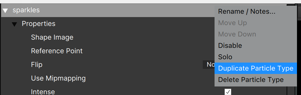
Note that it’s also possible to Rename, Solo and Hide using this menu, as well as Delete and rearrange particle types (Move Up/Down) if the emitter contains more than one particle type. Note: Move Up/Down is only available in 2D projects, and is not overly useful for particle types.
Super emitters work similarly in that you can create a new “basic” free emitter type using the “Add New Free Emitter Type” menu (it may show as “Add New Emitter Type” in some versions), and can duplicate an existing free emitter type, delete free emitter types, hide them, etc.
Note that the order of particle types and free emitter types usually does not make much difference, but there can be some rendering differences in some cases.
Make Super Emitter
To convert a regular emitter into a super emitter, use the emitter hamburger/context menu “Make Super Emitter” function:

If your project contains a super emitter, you can add a regular emitter to that super emitter using the “Add to Super Emitter…” menu item:
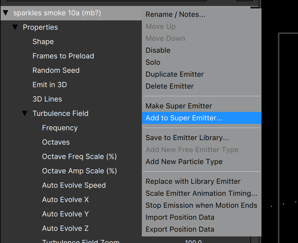
Note that option is only available if there is a super emitter in the project, and displays only for regular emitters.
A dialog showing all available super emitters will show:
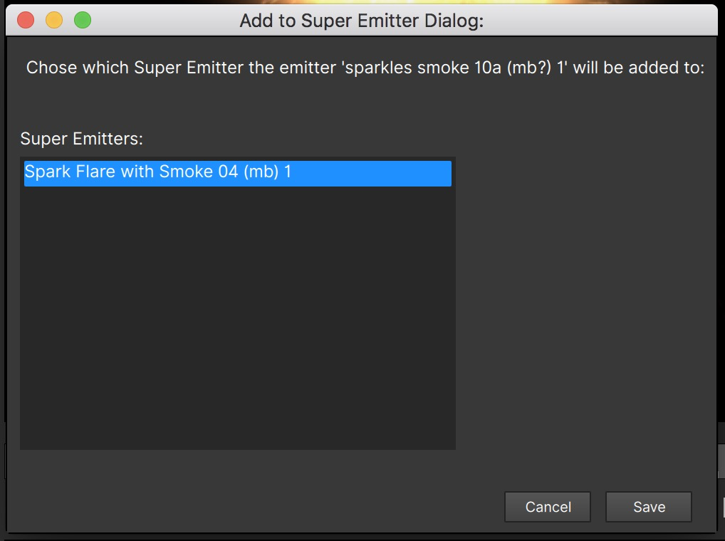
Note that the Free Emitter Type added to the super emitter will have the same name as the emitter that you added, and the original emitter will still be present in the project.
Note that there is no way to extract a regular emitter from a super emitter.
Creating An Emitter from Scratch
One of the advantages of Particle Illusion is its huge preset library. It’s much easier to start with a preset and then modify it to make it your own than it is to create one from nothing, but there are times when you might want to create an emitter without using a preset.
Technically this is not possible, as there’s no concept of an “empty” emitter in Particle Illusion, but starting with the 2021.0 version, some “Basic” emitters have been included that allow you to start from a nearly empty emitter.
If you do an emitter search for the word “Basic”, you’ll see a small collection of “Basic” emitters shown in the “Emitters_2021.0” library:
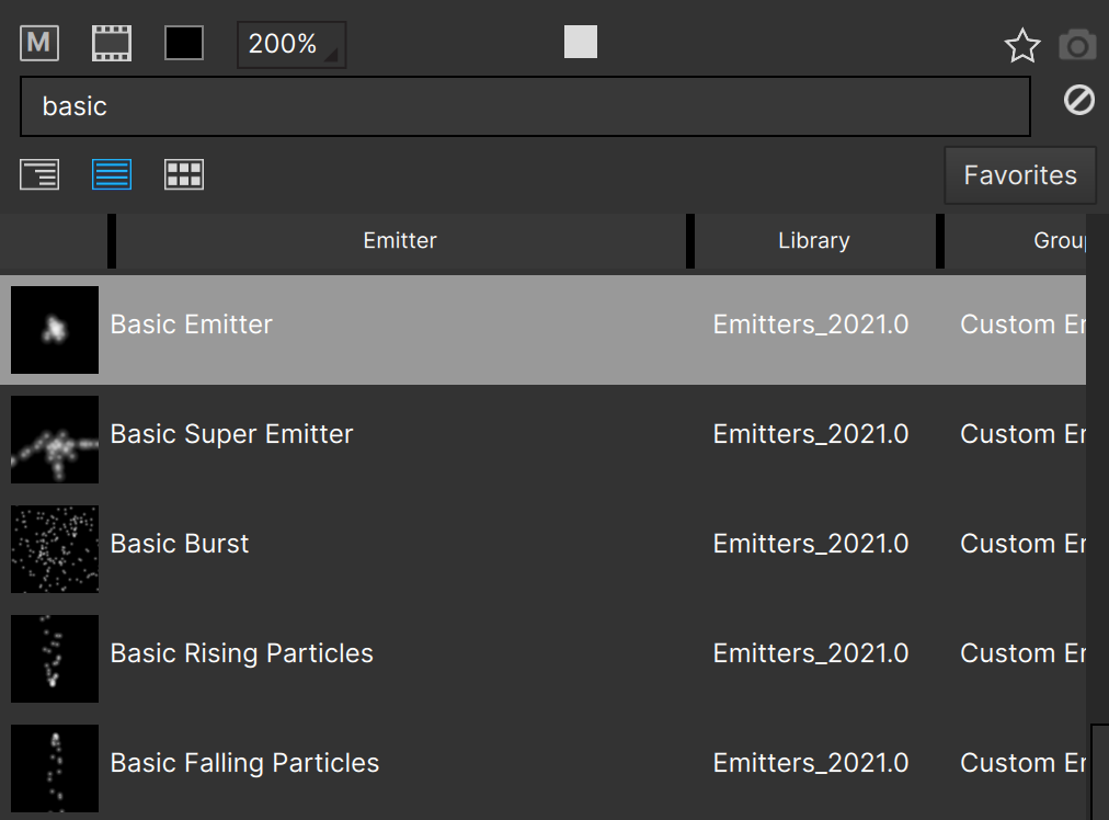
These five emitters are as close to a blank slate as you can get in Particle Illusion, and will let you create a custom emitter from scratch.
(Note that these are also included in your “Custom” emitter library – if you haven’t deleted them.)
Composite View (“Stage”) Controls
The Composite View or “Stage” is pretty straightforward, but there are some controls in the upper left corner of this view that require some explanation:
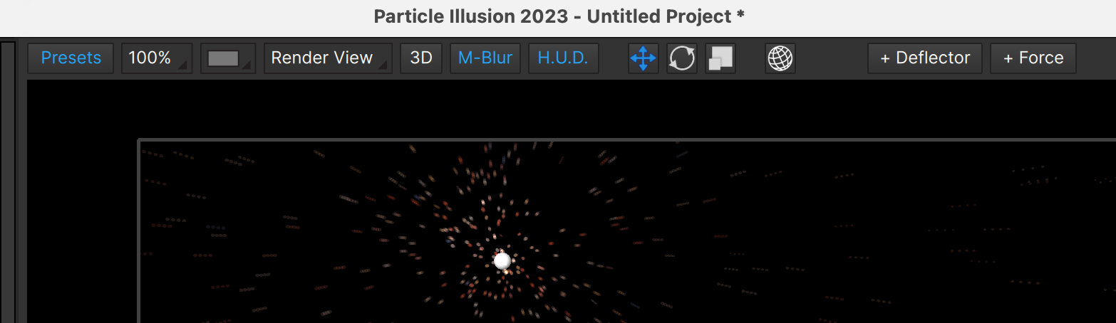
From left to right…
Presets: An easy way to show/hide the Emitter Libraries view and Preview.
Zoom: Sets the zoom level for the Composite View.
Preview Background: Select compositing over Black, checkerboard (which shows transparency), Source Frame, or Source Video. Note that the options in this list are ordered by performance, with fastest at the top and slowest at the bottom. (Source Frame and Source Video are only available in Particle Illusion Pro.)
When running as a plugin, the “Source Video” option will be automatically selected each time Particle Illusion opens, as this is the most common usage case; you’ll want to see the particles over your source.
View Selector: Enabled only in 3D projects, and lets you switch between the Render (camera) view, Top, Left, Right, Bottom, and World Views — essential when trying to position objects in 3D space.
2D/3D: This allows you to switch between 2D and 3D modes.
Motion Blur: toggles motion blur for the Composite View. Performance is increased with motion blur off. (Note that the motion blur settings are in the Project Settings dialog covered later).
H.U.D.: Toggles the “heads up display”. When turned on, the overlays for object, position path, etc. are visible. When off only the particles are visible. Also note that the ground plane in 3D views is controlled by this button.
Translate Mode: For moving objects in the Stage with widgets.
Rotate Mode: For rotating objects with widgets.
Scale Mode: For scaling some objects with widgets.
World Coords: Toggles between Object and World coords when translating rotated objects.
+ Deflector: Used to add a deflector object to the project. (See below)
+ Force: Used to add a force object to the project. (See below)
The upper right corner of the view displays some useful information too:
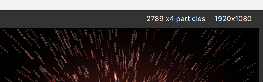
The number of particles is displayed here, and if motion blur is turned on you’ll see the frame multiplier. In this example motion blur is set to 4 frames, and the multiplier reminds you that the particles are being drawn 4 times.
The project resolution is shown here also. (Note: click the project resolution as a shortcut to open the Project Settings dialog so the resolution or motion blur settings can be changed.)
Note that the particle count is usually the main factor in determining performance. If your project is too slow, particle count is most likely too high — reduce the “number” value or disable emitters.
(The number of motion blur frames and the project resolution are both set in the Project Settings dialog, unless running as a plugin, when resolution is set by the host, and motion blur frames might also be set there.)
Interacting with the Composite View (Stage)
Besides the zoom and motion blur controls discussed above, there are other ways of controlling the Stage.
- Scroll/Pan the Stage by holding the spacebar then clicking and dragging in it.
- Zoom In using Cmd+ on (macOS) or Ctrl+ (Windows)
- Zoom Out using Cmd- on (macOS) or Ctrl- (Windows)
- Toggle Motion Blur using Cmd-B (macOS) or Ctrl-B (Windows)
- The “F” key will Fit the Stage to the View size
You can also zoom using the mousewheel or trackpad when the mouse cursor is positioned over the Composite View.
Using After Effects Camera (Plugin version only)
Besides the built-in camera when Particle Illusion is set to 3D mode, it’s possible to use the After Effects camera:
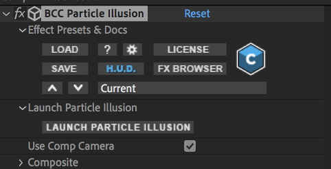
Just check the “Use Comp Camera” parameter before launching Particle Illusion.
Then inside PI, you won’t see any built-in camera controls, but the view in the Stage will be set to whatever the AE camera is for that specific frame.
Note that the other indication that the AE camera is being used when in the Particle Illusion application is that any camera animation will automatically be applied in the Stage.
(Note also that changes to the 2D/3D button will not make a difference.)
Motion Tracking and Masking (Plugin version only)
When Particle Illusion is used as a plugin, motion tracking and masking are available, powered by Continuum’s integrated Mocha tracker.
With this tracking you can essentially “pin” an emitter to a feature in your shot — for instance a train’s smokestack — moving it automatically without requiring you to manually animate the emitter position.
To track the position of an emitter, select “Emitter” for the Transform / Tracking parameter in your host application:
![]()
Then expand the “Motion Tracker / Mocha” group and click the “Mocha Motion Tracker” button:
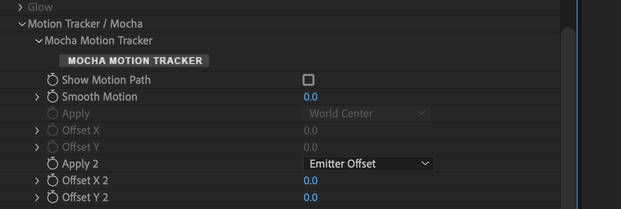
This opens the Mocha interface, where you can then track the emitter position:
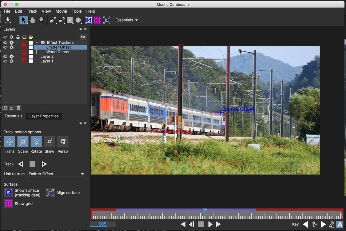
The details of how to use Mocha are provided elsewhere, but the key concept to understand when using it with Particle Illusion is that the “Transform / Tracking” parameter must be set correctly:
- “Emitter” if you want to track an emitter position in a shot with a stationary camera
- “World” if you want to track the camera movement only (with emitters that don’t move or that you’ll animate manually)
- “World + Emitter” if you want to track both camera movement and emitter position
Mocha not only provides tracking, but also masking. When in the Mocha interface, there are several ways to draw masks: freehand, as X-splines, with the magnetic tool, and more.
Once the masks are drawn, they also get tracked by Mocha, reducing or eliminating any manual repositioning. There are parameters for feathering, inverting the mask, and more:
Both the Mocha tracking and masking are essential features to integrate Particle Illusion effects into your projects.
Particle Masking (Plugin version only)
The Mocha masks are traditional composite masks, but there are others ways to use masks with Particle Illusion.

There are three ways to use a mask:
“Particle Creation” - The particles are created only in the non-zero part of the mask. After creation the particles live out their lives normally, and can move outside the mask area.
“Render Mask, Standard” - The mask is used as a standard composite mask, with particles visible only inside the mask area. Particles will be clipped by the mask. (This type of masking is possible with most hosts, but is handy when rendering directly from Particle Illusion.)
“Render Mask, Full Particles” - Similar to the previous option, but particles are not clipped: the full particle is always drawn. (Larger particles show this more clearly.)
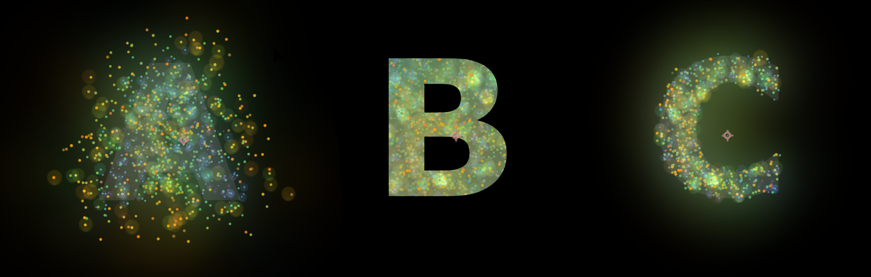
A: “Particle Creation”, B: “Render Mask, Standard”, C: “Render Mask, Full Particles”
The source for the particle mask can be either a Layer/Source input, or the Continuum PixelChooser:
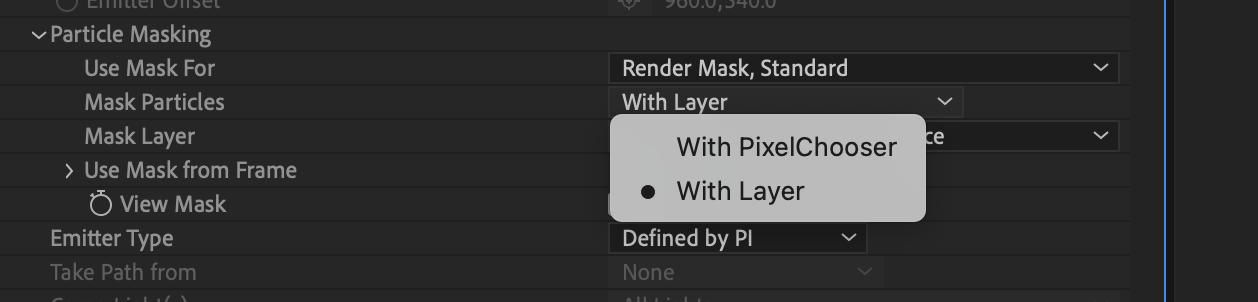
“Layer” (or source input depending on your host) is the simplest way to access a mask, while the PixelChooser gives you many more options, including preset shapes, gradients, choosing specific channels, adding blurs, and more:
![]()
Note that regardless of the mask source, Particle Masking can only use the mask from a single, static frame, set using the “Use Mask from Frame” parameter.
Composite Style / Apply Modes (Plugin version only)
Also when used as a plugin, Particle Illusion can be applied using a variety of transfer modes. The default setting is “Direct (Classic)”, which composites the particles directly over the source layer — this is the method used by the legacy particleIllusion application.
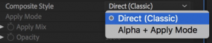
Using this mode gives you access to some basic color correction parameters:
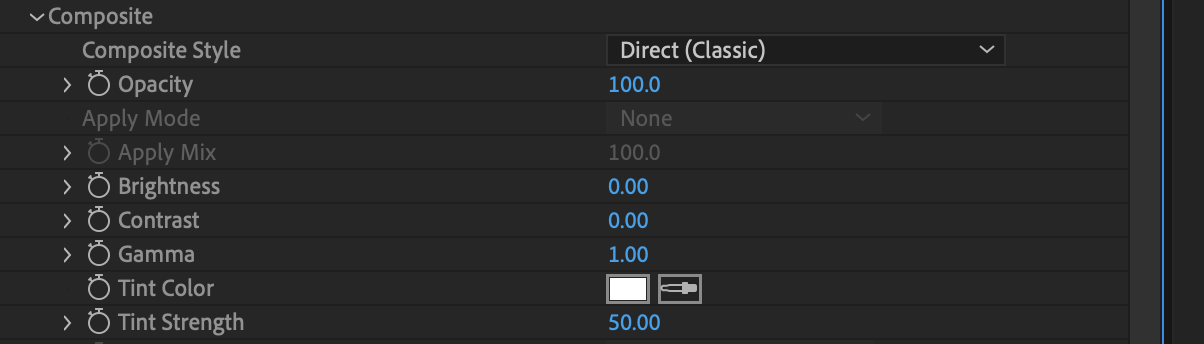
Although this “Direct” composite style may be ideal for some projects, a wide variety of apply modes become available once the “Alpha + Apply Mode” Composite Style is selected:
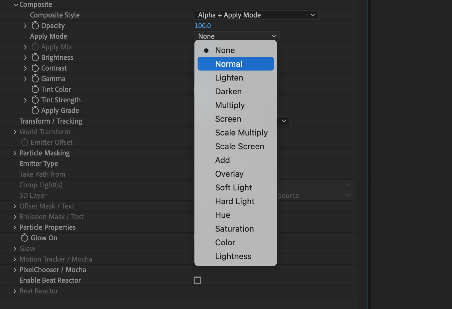
With an apply mode selected, you then have the ability to not only mix the selected mode with Normal mode using the “Apply Mix” value, but you can adjust the Opacity of the effect too — both of these give you a huge amount of control in blending the particle effects into your project.
You can also adjust Brightness, Contrast, and Gamma regardless of which Composite Style is chosen, but when “Alpha + Apply Mode” is selected you can also choose to apply these adjustments to just the particles, or to the composition.
Particle Properties (Plugin version only)
Under the “Particle Properties” section you have access to some of the Particle Illusion native parameters:
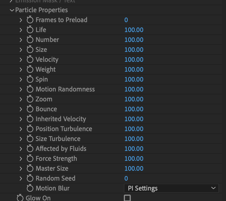
These are provided not just for convenience — as they let you adjust some aspects of the particles without having to jump back into the PI interface — but also allow you to animate and utilize your host application’s scripting capabilities.
Note that it’s best to think of these parameters as an additional level of scaling factor being applied; they can’t add something that is not there in the emitter already. For example, if the particles in the emitter have a velocity of 0, the “Velocity” parameter in this “Particle Properties” section will have no effect: 100% of 0 is still 0.
Glow (Plugin version only)
You can add glow to the particles by clicking “Glow On”:
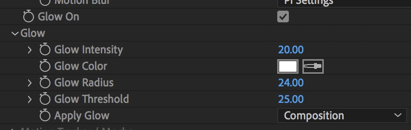
Once enabled you can adjust intensity, color, radius and threshold, and when using “Alpha + Apply Modes” as the Composite Style you can choose to apply the glow to the particles alone or the composition.
Beat Reactor (Plugin version only)
When talking about the Particle Properties above, it was mentioned that you can animate those parameters or use the host’s scripting capabilities. Even if your host does not have scripting you can still make particles react automatically to an audio track by enabling Beat Reactor:
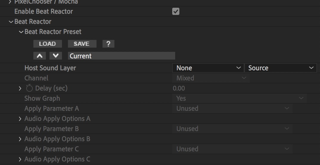
After selecting an audio layer (or external audio file based on which host application you’re using), you use Beat Reactor to set frequency ranges and tie them to specific Particle Illusion parameters.
Beat Reactor works in the same way in Particle Illusion as it does in the other Continuum effects that contain it — more information on Beat Reactor here.
Tip: if you want to make the particles “pulse” in time to the audio (change size to the beat), control the “Master Size” parameter, not “Size”.
Note that if you use Beat Reactor to drive specific Particle Property parameters, and have manually animated those same parameters (or have used your host’s scripting to animate them), results may be unpredictable.
Path/Light/3D Layer Follow (plugin version, AE only)
In After Effects you can have Particle Illusion emitters follow a path (mask/text) or attach to Lights or 3D layers:
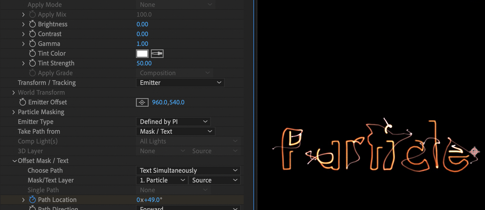
To enable this feature in the Particle Illusion plugin in After Effects, set “Transform / Tracking” to “Emitter”, then the “Take Path From” options available are Comp Lights, 3D Layer, or Mask/Text:
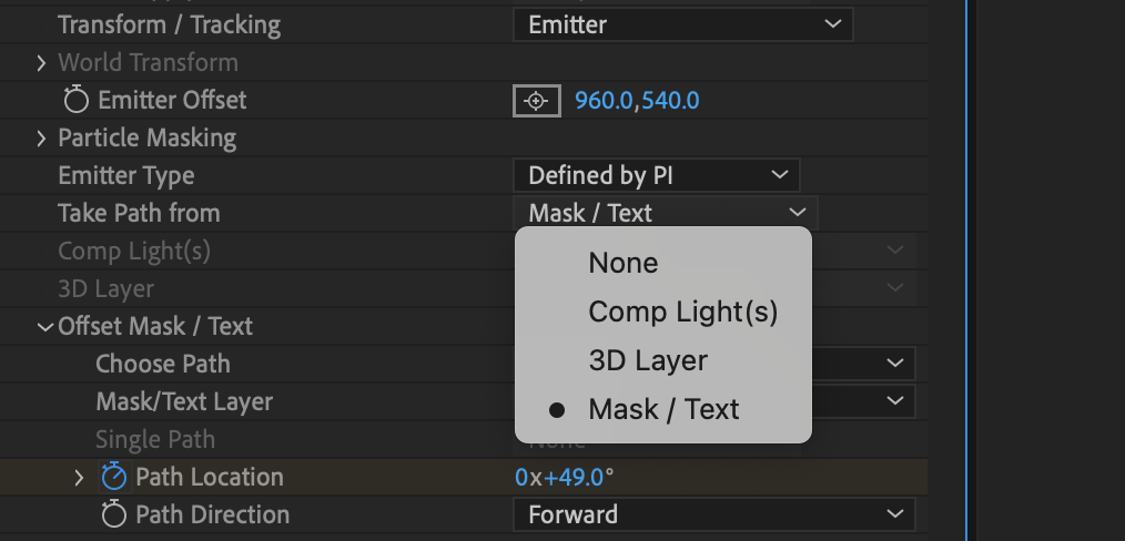
With “Mask/Text” selected, the parameters in the “Mask/Text” section are enabled, and you have several options in the “Choose Path” parameter:
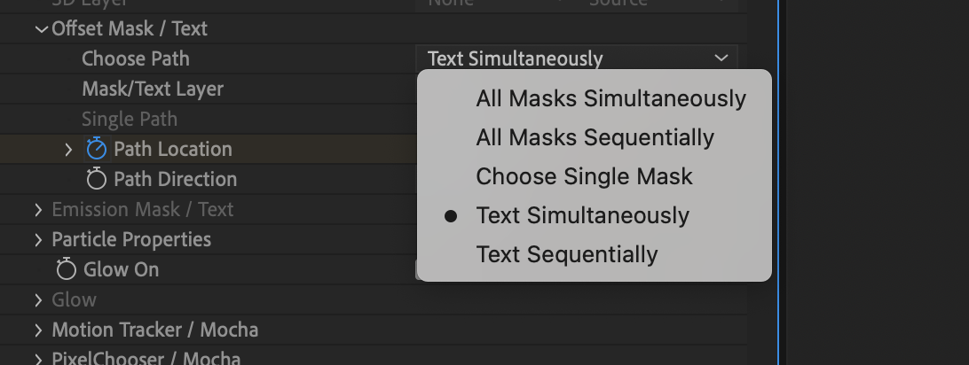
As seen you can choose to follow all masks simultaneously or sequentially, choose a single mask to follow, or follow text simultaneously or sequentially.
(Note that all of these options are always enabled even if masks or text layers are not present in the composition so you’ll have to know which option you need.)
To trace all text characters or masks at the same time, choose the “Simultaneously” version. This will make copies of the emitter for each letter (or mask).
Next you select the Mask/Text Layer:
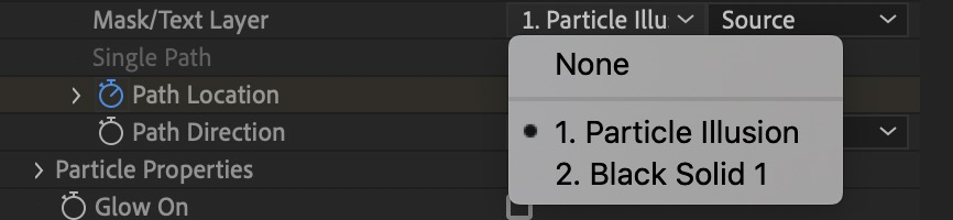
This allows you to have the text/mask on a different layer — the chosen layer does not even need to be visible.
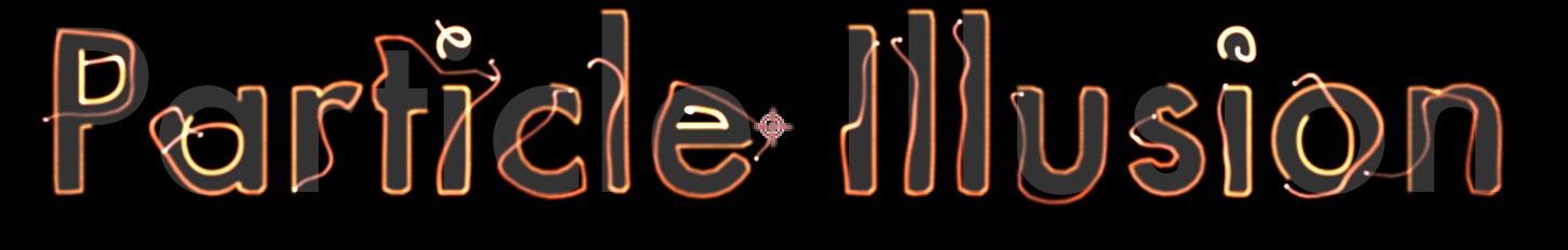
Note that because of the multiple copies of the emitter, you may want to use the “Number” parameter to decrease the number of particles created.
Animate Path Location Parameter
In order to actually trace the letters (or other paths), you need to do one more step: animate the “Path Location” parameter so it starts at 0º and then some time later increases to 359º (or 1 revolution). You can set it to multiple revolutions if you want the emitter(s) to loop around the path multiple times.
You can use the Path Direction parameter to set the direction of tracing, or even have it trace one direction then reverse.
If you instead want each character or mask to be traced in turn (one after another), choose the “Sequentially” option. Remember that the emitter position is being offset here, so if the emitter is moving too quickly — when tracing out a long text string for instance — the details won’t be preserved:
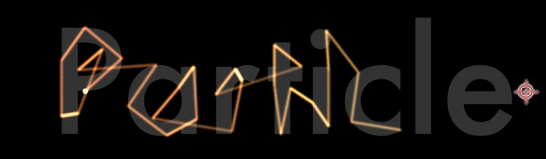
The answer is to either have the “Path Location” parameter animate slowly, or only use masks that don’t have small details or corners. (Or stick to the “Sequentially” option.)
Comp Lights and 3D Layer are similar to Mask/Text, except the emitters are attached to the selected objects — there is no “tracing” involved — so many of the parameters that were used for mask/text are disabled.
There are several options for selecting which lights will be used:
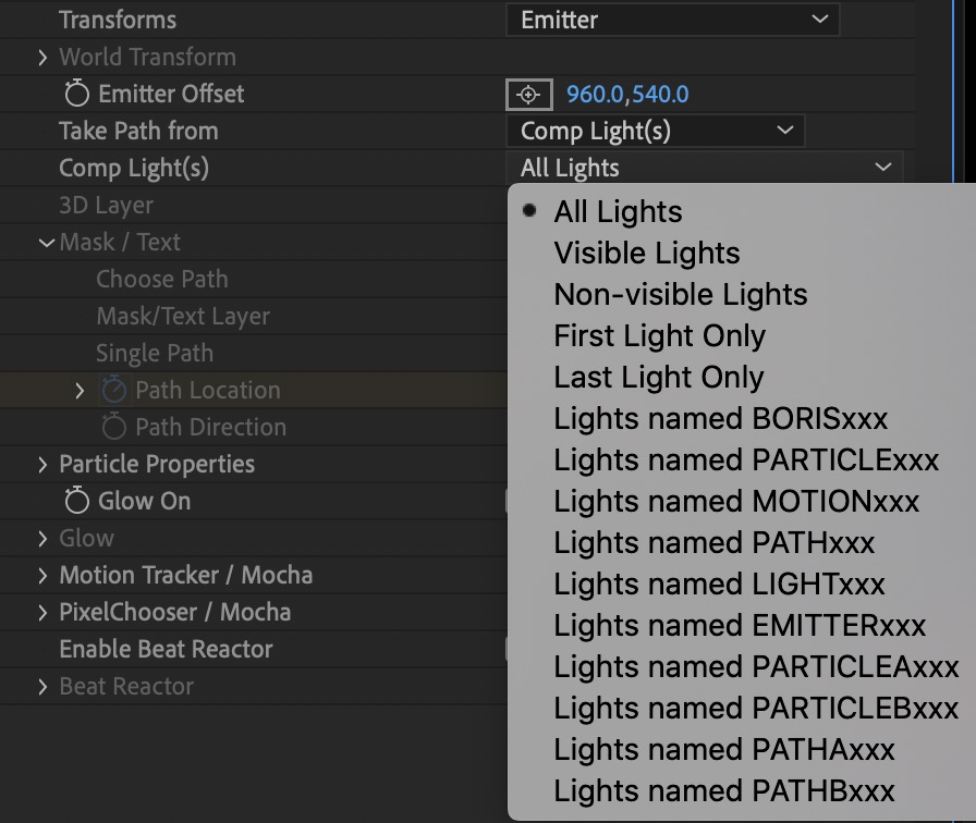
Note that if your comp has several lights that will be used for emitters you may want to decrease the “Number” parameter as multiple copies of the emitter will be created automatically.
For 3D layer, you can select a single layer to use for attaching an emitter.
Mask/Text Emission (plugin version, AE Only)
In After Effects you can not only animate emitter position using masks and text (as seen in the previous section), you can also use masks and text as emission sources.
The “Emitter Type” parameter determines if the emitter will be as defined by PI, or if it will use a mask or text for emission instead:

After selecting “Mask/Text”, the “Emission Mask/Text” parameters are enabled:
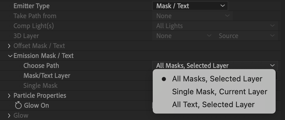
The emission options are self-explanatory: “All Masks, Selected Layer”, “Single Mask, Current Layer”, or “All Text, Selected Layer”.
For the options based on “Selected Layer”, use the “Mask/Text Layer” selector.
Here’s an example using “All Text, Selected Layer”:
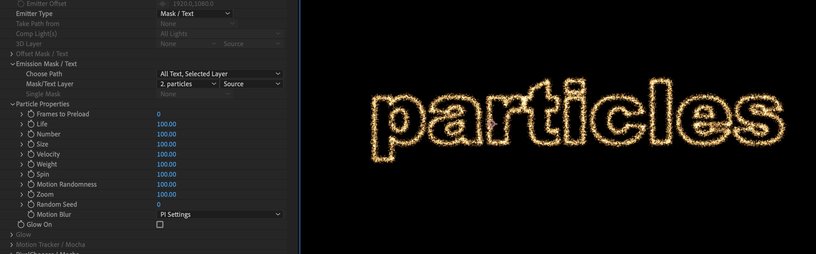
Note that it doesn’t matter what the emitter shape was in PI: point, line, sphere, 3D Model. Once you select Mask/Text Emission, it is internally converted into a “line” emitter (that is then fit to the mask or text path). Switching back to “Defined by PI” will restore the original emitter shape.
Important: Using masks or text for emission can greatly increase the number of particles that are created, so you may want to decrease the “Number” parameter in the Particle Properties section significantly before selecting mask/text emission.
It’s possible to use both Mask/Text emission and Mask/Text position offset at the same time – for instance to have particles emitting from text, then having that text move along a separate path.
Particle Influencers (Deflectors and Forces)
Although Emitters are the main objects you’ll be using in Particle Illusion, there are two other types of objects that will influence particles and make your projects more interesting: Deflectors and Forces.
Deflectors
Deflectors are objects that particles will hit and bounce from. They consist of one or more line segments with parameters to control the amount of bounce and more.
To add a deflector, click the “Deflector” button above the Composite View…
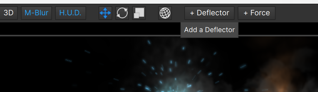
…and a deflector made up of two points will automatically be added to the center of the stage:
To move it, click and drag the endpoints:
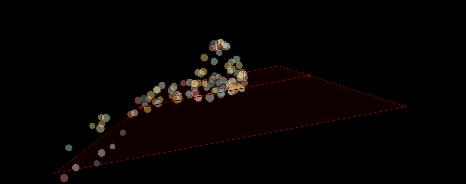
To add points to a deflector, you have two options:
- Add a single point: Alt-click (Windows) Option-click (Mac) anywhere on the deflector line.
- Add many points: Alt-click (Windows) Option-click (Mac) on the last point of the deflector. This puts you in “add point mode”, where each click adds a point. Double-click to add the last point and end, or press ESC to exit without adding a last point.
Deflectors are true 3D objects, with these parameters:
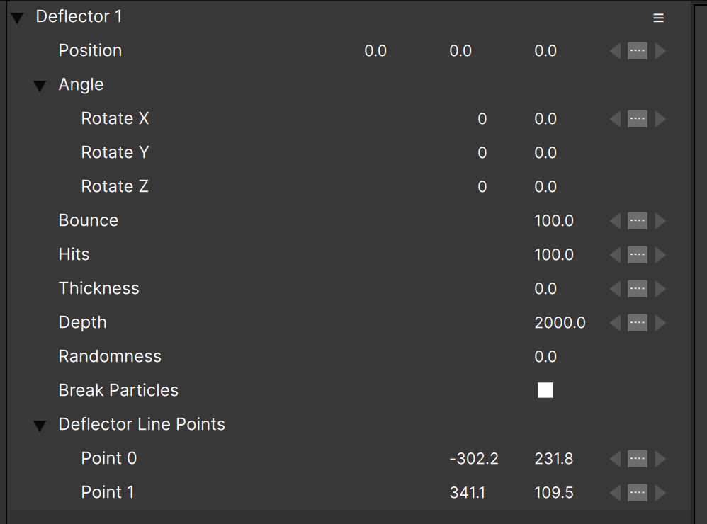
Position —Adjust or animate the position of the deflector in 3D space.
Angle — Set the angle of the deflector or rotate it in 3D space.
Bounce — scales the amount of bounce that particles have when colliding. Note that if the particle type or emitter “Bounce” values are zero, adjusting this will have no effect.
Hits — determines what percentage of particles will hit. Usually you’ll leave this at 100 but lower values might be desirable in some circumstances.
Thickness — allows you to increase the thickness of the deflector “line”, which can be useful when you want to simulate particles bouncing off a plane instead of a line. (Probably only useful in 2D projects.)
Depth — Set the depth of the deflector plane(s) in a 3D project.
Randomness — adds a random component to the bounce vector, which can result in a more realistic simulation especially for natural effects like water.
Break Particles — when checked particles will break when they hit, and more parameters are revealed:
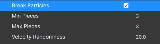
Min Pieces and Max Pieces determine how many pieces are created. You can set the minimum to “1” so some particles do not break on every collision.
Note that Min Pieces must be set less than or equal to Max Pieces.
Velocity Randomness — adds some variation to the broken particles’ bounce vector. When 0 or very small, the particle pieces will be on top of each other.
(Remember that there is a Particle Type Property that can be used to keep certain particles from breaking on deflectors.)
In addition to the Position parameter that can be animated, each point that makes up the deflector will display its position in the controls view under the “Deflector Line Points” group:
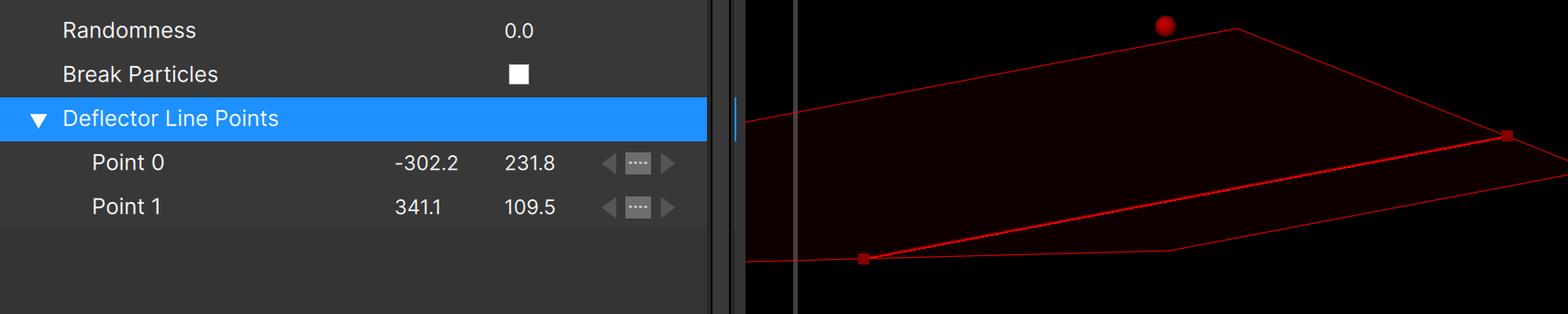
You can animate the position of these points in the same way as emitter position can be animated (by dragging in the Stage with the appropriate animate buttons set, by using the “create key” button, etc.)
A few things to note about deflectors:
- When bounce is 0, particles will “sink” through a deflector. (To fix this, set bounce to 0.1 or 1%)
- Only moving particles will hit a deflector. If the particles are not moving but the deflector is, collisions will NOT happen.
- With high Position Turbulence values, deflectors may not work as expected (or it may be very difficult to see that they are working)
Forces
Force objects apply an acceleration to any particles that enter their area, a bit like wind (or a magnet depending on the force type). Force objects can also provide the complex, organic movement of fluid dynamics to your project.
To add a force, click the “Force” button above the Composite View/Stage…
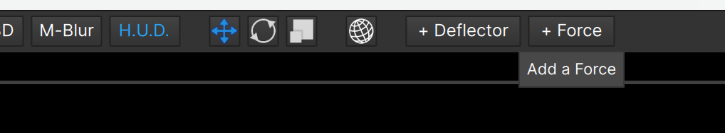
…and a Force object will be added slightly offset from the center of the Stage (to make it easier to drag and reposition).
There are three types of force objects in a 2D project: Area, Grid, and Point. The type is set using the “Type” parameter, with “Area” being the default:
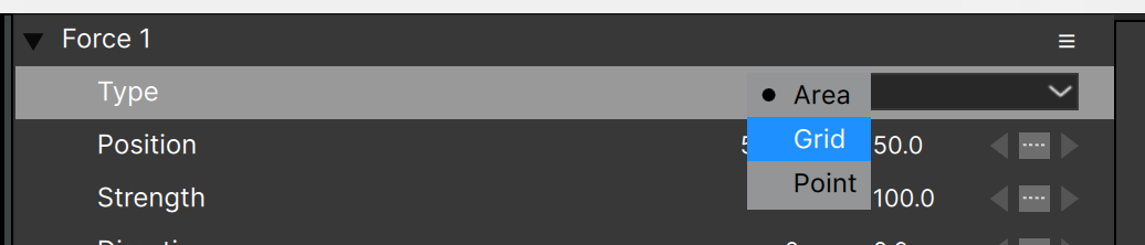
In a 3D project the types list is modified; you can choose from Box, Box Grid, and Sphere:
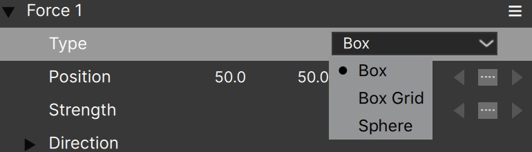
Area Forces
Area Force objects are rectangular, with dimensions set by “Width” and “Height”:
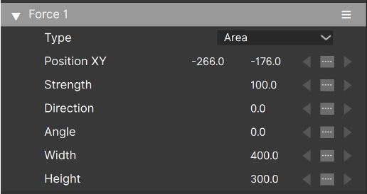
The “Direction” parameters sets the angle of the force, and the “Strength” determines how much force is applied.
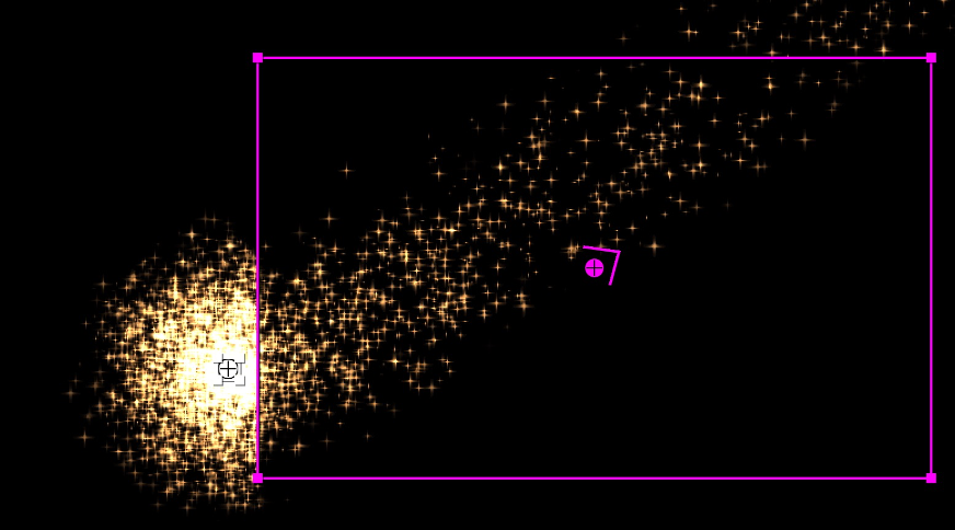
Note that “Strength” can go negative, and will then move particles opposite to the direction parameter.
Grid Forces
Grid Forces are rectangular like Area Forces, but the rectangle is divided into a grid of cells:
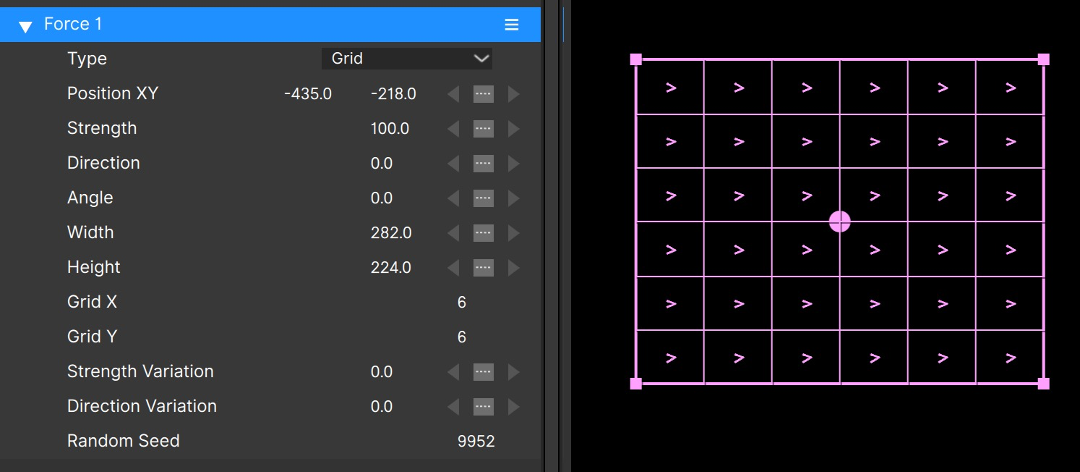
In addition to the parameters that the Area Force has (Strength, Direction, Angle, Width, Height), a Grid Force has Grid X and Grid Y parameters to set the number of horizontal and vertical divisions, and Variation parameters for Strength and Direction.
With Strength Variation and Direction Variation both set to “0”, a Grid Force behaves exactly like an Area Force: all particles that enter it are accelerated the same amount, in the same direction:
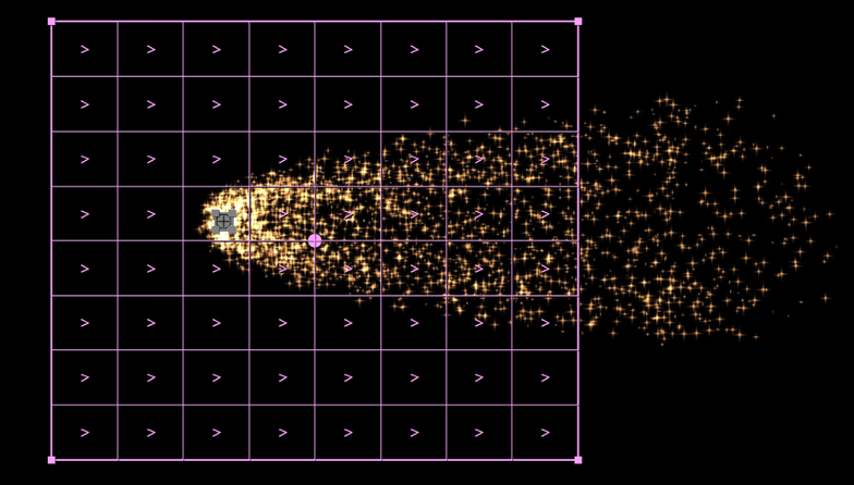
When Strength Variation or Direction Variation are non-zero though, that’s when things get interesting. Let’s start with Direction Variation, as it has the biggest impact. With Direction Variation set to 90 (degrees) and an 8×8 grid, this is what we get:
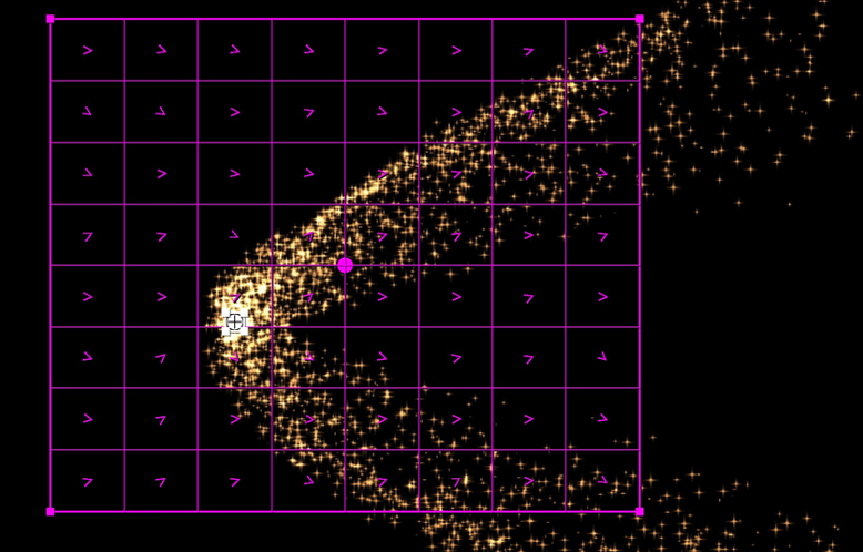
The emitter was moved slightly from the previous image to help illustrate a point: each cell of the grid now has a different direction, as indicated by the arrow in each cell.
With Direction Variation set to the maximum (360 degrees), each cell will point in a random direction. Depending on the placement of the emitter, the Strength value, and a few other options (Strength Variation, the velocity of the particles, number of grid cells, etc.) you can get very complex, organic particle motion:
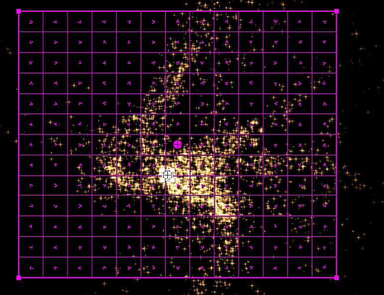
The motion becomes even more interesting if the emitter and particles move into different cells over time. For example animating the Position, Angle or Direction of the Force can result in very sophisticated particle motion.
Note that the “Random Seed” parameter can be changed to get a different pattern for Strength and Direction Variation.
Point Forces
The final type of Forces are Point Forces. A Point Force is quite different from Area and Grid Forces in that it is circular, not rectangular:
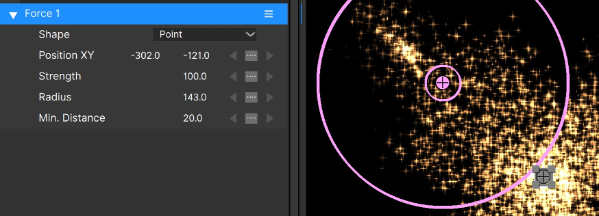
Also, it does not have a “Direction” parameter as all particles within its active area are accelerated toward the center point. You can think of Point Forces as “attractors”.
Since particles that pass very close to or even through the center point will have very large acceleration, Point Forces have a “Min. Distance” parameter that creates a smaller circle of no additional acceleration — essentially it makes it easier to avoid “stray” particles that have huge velocities.
In the same way that a negative Strength value will reverse the acceleration direction in Area and Grid Forces, a negative Strength turns a Point Force into a particle repeller:
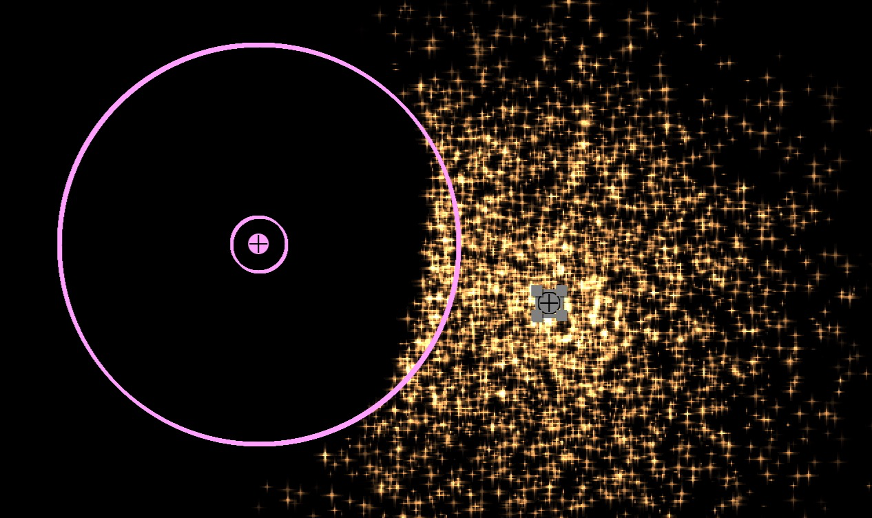
This makes Point Forces ideal for pushing particles out of the way.
Box, Box Grid, and Sphere Forces (3D)
In 3D the “Box” type is almost identical to the “Area” force, but it adds a Depth parameter. So too the “Box Grid” type is almost identical to the “Grid” type, and “Sphere” is the 3D version of the 2D “Point” force — they behaved identically but in 3D.
Adding Forces to your projects, especially Grid and Point Forces, will give you advanced particle motion that you won’t be able to get any other way in Particle Illusion.
Note that Force objects can be saved in Particle Illusion project files, as host presets (loadable through the FX Browser), but they cannot be added to an Emitter Library.
Turbulence
Earlier we mentioned using the Direction parameter to give motion to particles, or to vary that direction using Direction Variation in Grid/Box Grid forces.
A newer (since v2023.5) method of varying the Direction is with the use of the Direction Turbulence parameter. Think of Direction Turbulence as a higher resolution, more organic version of Direction Variation. Set to “100”, the force direction is set entirely by the turbulence field, with lower values giving a blend with the Direction parameter vector.
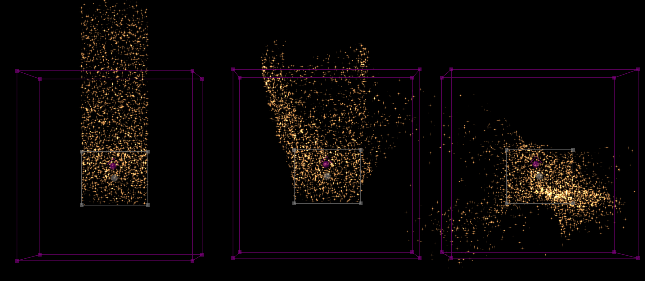
Turbulence has been available in Emitters for several releases, and it is virtually the same in Forces: the “Turbulence Field” parameters determine how the turbulence looks and evolves:
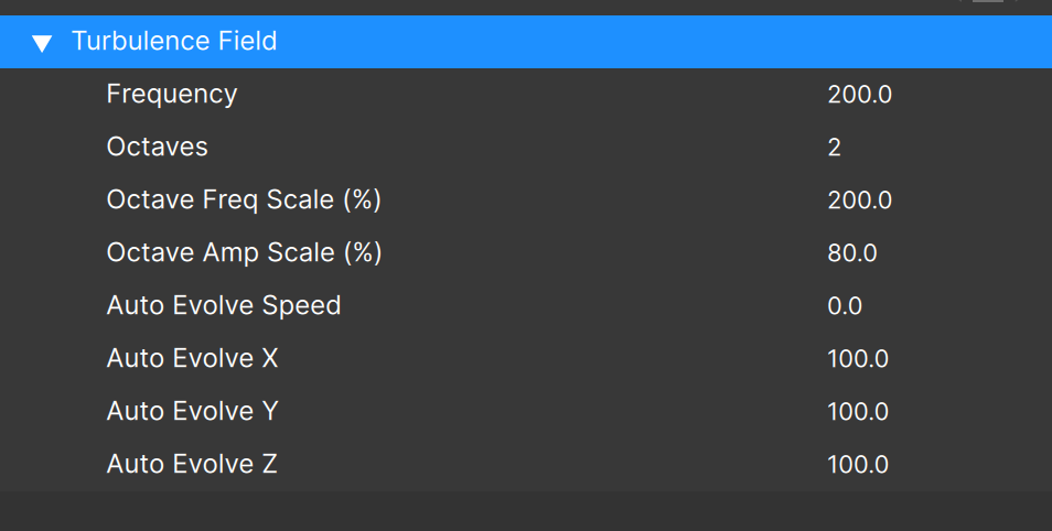
The two parameters with the most effect in Forces are “Frequency” and “Auto Evolve Speed”, so that’s a good place to start.
See the Emitter “Turbulence” section for more details.
Note that Direction Turbulence may make Grid/Box Grid forces less useful.
Edge Softness
Particles that enter the force object area are immediately affected by the force. In some cases – such as when the force strength is quite high, or when a particle moves into or out of a fluids object – this can be unattractive or undesired:
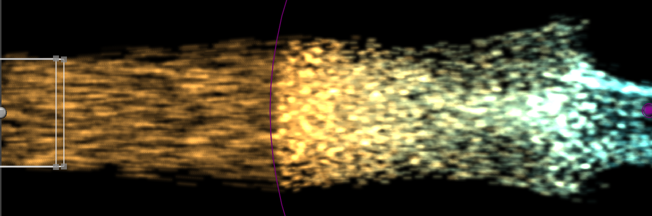
The “Edge Softness” parameter softens the transition at the edge of the force object, so particles more smoothly move into and out of its influence. Here’s the same example but with “Edge Softness” set to “40”:
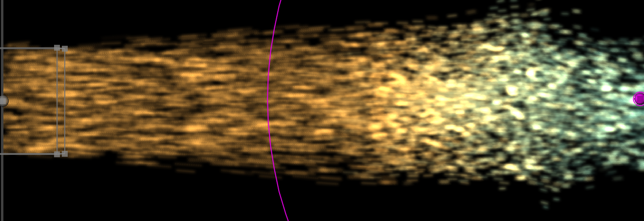
Fluid Dynamics
To enable fluid dynamics in a force object, simply check the “Enable Fluid Dynamics” force parameter:
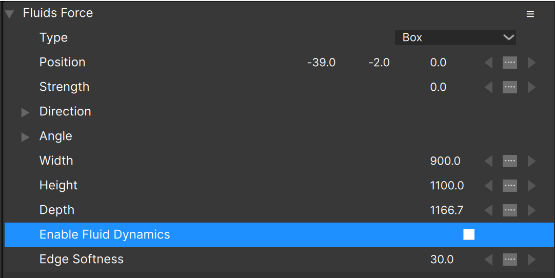
(Note that it is possible to have only a single fluids force object in a project. Once fluids is enabled for one force, all remaining forces won’t show the “Enable Fluid Dynamics” parameter.)
Once enabled, the fluids parameters will be displayed:
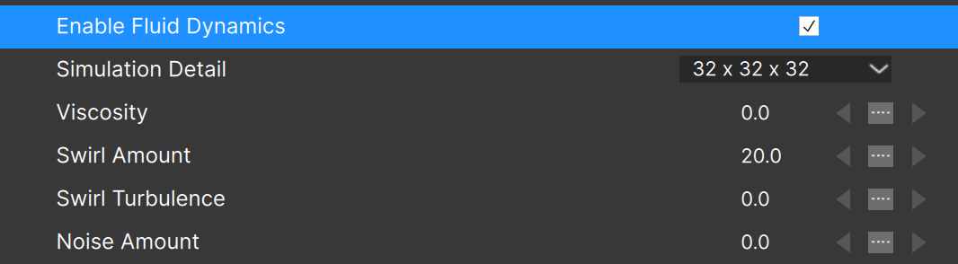
“Viscosity” sets the thickness of the fluid, where higher values restrict the flow more and allow less turbulence. Think of 0.0 as more like water, and higher values acting more like the particles are moving in oil:
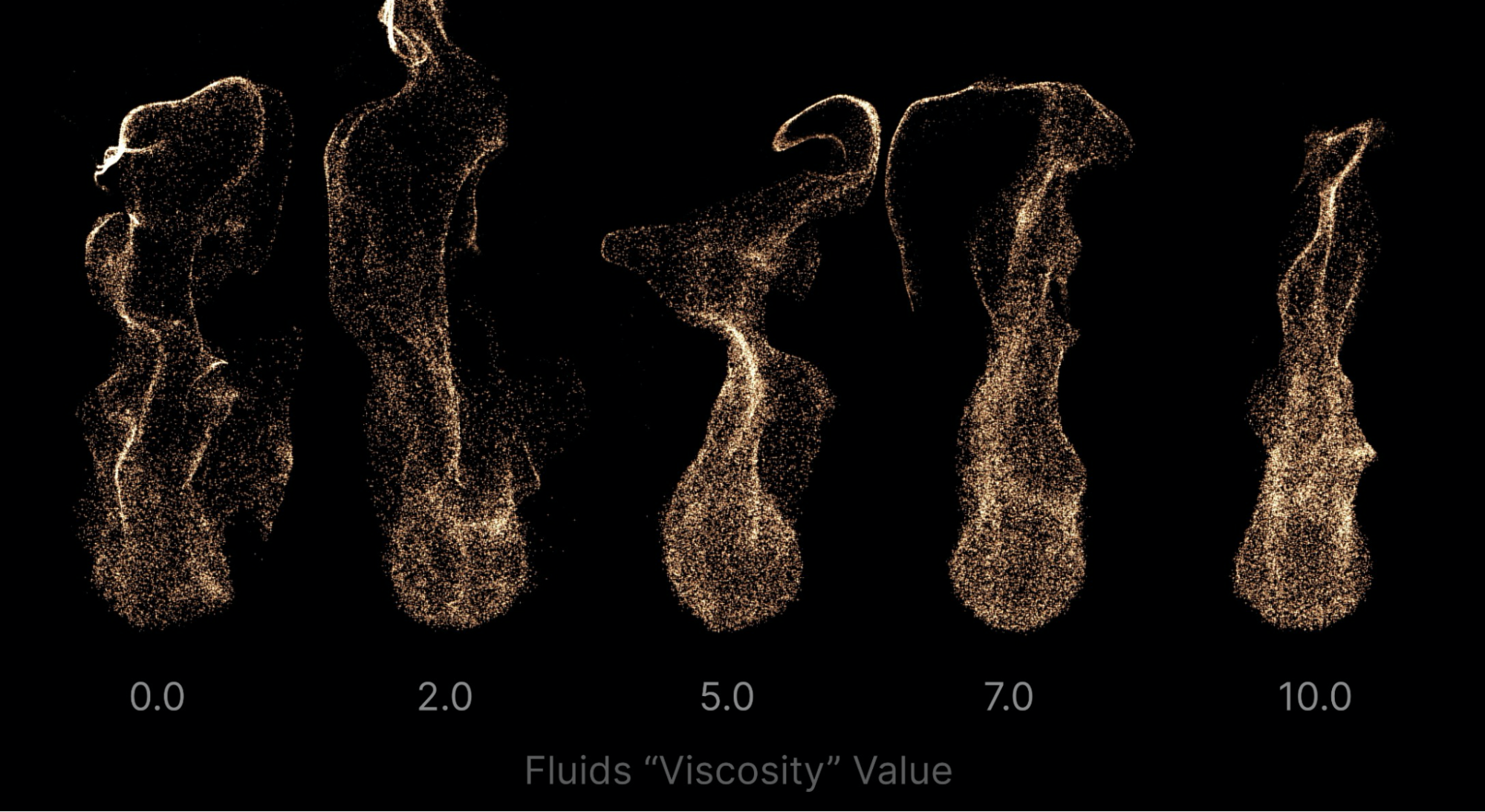
“Swirl Amount” adds turbulence to the fluids. In projects with a single emitter and no additional force objects, the fluids might move in a fairly calm “stream” — there’s nothing that stirs things up. Adding some “Swirling” can help give the particles that organic turbulent flow that you’d expect in a fluid simulation.
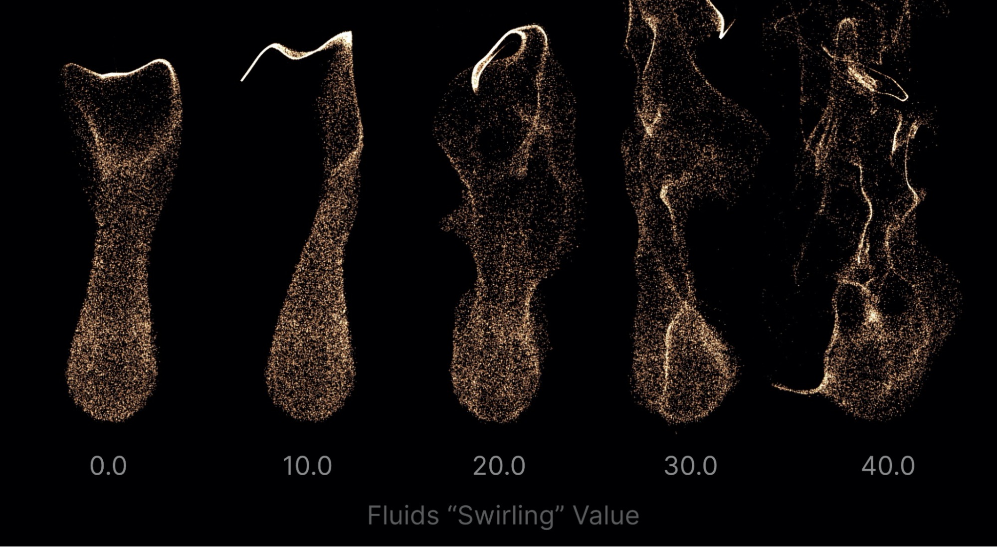
Note that if “Swirling” is set too high, the simulation can become unstable, causing particles to move in unexpected ways. For this reason it’s best to keep “Swirling” to values of 40.0 or less. When particles are moving very quickly though, higher values of “Swirling” may be required.
“Swirl Turbulence” will add a secondary turbulence that can add more “detail” to the swirls. (Lower values seem to produce the best results, so don’t set this too high.)
“Simulation Detail” controls the resolution of the fluid simulation, with lower values calculating more quickly but giving less detailed results. In a 3D project you can choose from three levels of detail. Note that the highest setting does not always produce the best results — often the larger motion of lower settings is more appropriate.
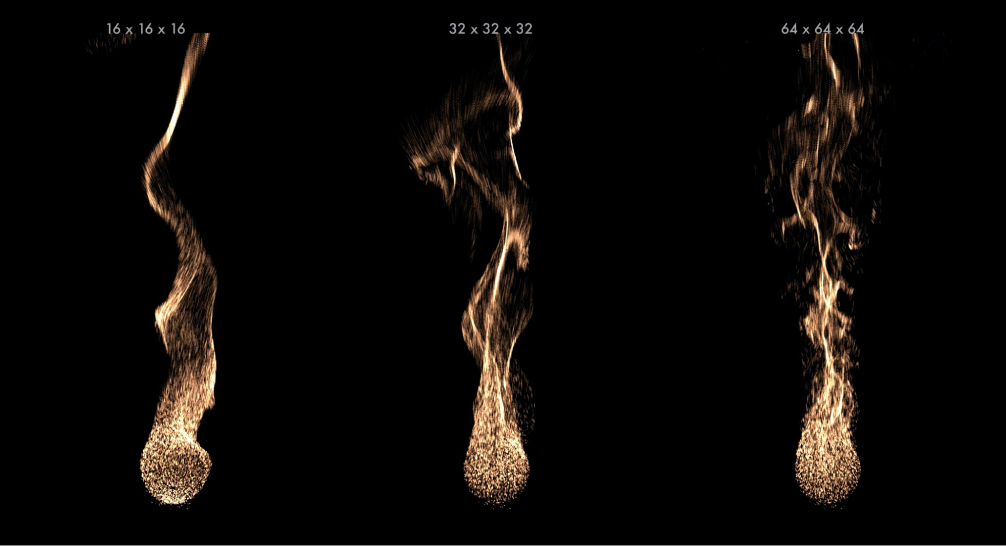
Fluid Simulation Motion
It’s important to understand that the motion of fluids in Particle Illusion is supplied completely by the particles themselves. Stated another way, it’s the particles that move the fluids. Therefore if your particles are not moving much, you won’t see much fluid motion either.
In practice this means that you may need to increase the velocity or weight of the particles when added to a fluids project.
Since forces act on particles, force objects can also be used to control the movement of the particles — and therefore the movement of the fluids. Note that the fluids force object is the biggest contributor to this — other force objects added inside a fluids force will need their strength values set quite a bit higher than that of the fluids force object to influence the particles.
The type of the fluids force object is quite important to the overall look of the fluids, so switch between the different types (Box, Box Grid, Sphere) to see the effect on the overall look.
Some things to keep in mind about fluids:
- Particles that move outside of the force area are no longer affected by the fluid simulation. (If you see some particles that seem to be moving too fast or are not swirling as expected like the rest of the particles, check to see that they aren’t moving out of the force area.)
- Box and Box Grid forces have a “depth” parameter that may need to be increased.
- A positive value for “Strength” in Sphere forces attracts particles to the center. With high enough values, can create an interesting “suction” or “down the drain” effect.
- A negative value for “Strength” in Sphere forces repels particles. This can help to create more dynamic “burst” type fluid effects.
- Animate the fluids force “Strength” between positive and negative to create more complex effects.
- The position of the fluids force can be animated.
Note: It is possible to have only one fluids force object in a project. Once fluids is enabled for one force, all remaining forces won’t show the “Enable Fluid Dynamics” parameter. This applies to Library Scenes too: if your project contains a fluids force already, the fluids force in a Scene will not be added to the project.
Affect Fluids and Affected By Fluids Parameters
Once fluid dynamics are enabled in a project, all emitters in the project will have a two new parameters visible, “Affect Fluids” and “Affected by Fluids”:
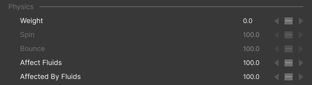
“Affect Fluids” allows you to set how much influence each emitter in a multi-emitter project will have on the fluid motion, and also allows you to scale the amount of motion an emitter provides. Lower values mean less influence, and a value of 0 means that the particles of this emitter will not contribute to the fluid motion at all. They will still be affected by forces, which will then move the fluids, and they are still affected by fluid motion, but their velocity and weight won’t change the fluids.
“Affected By Fluids” adjusts how much each emitter’s particles are influenced by fluids. When set to values less than 100 (percent), the particle motion for this emitter is a mix of the original particle motion (without fluids) and the motion of the fluids. Setting it to 0 will make this emitter “ignore” fluids completely – at least with regards to particle motion.
Using these two parameters, it’s possible to have particles that do not contribute to the fluid motion, but are moved by the fluids. Conversely, it’s possible to have particles that move the fluids but are not moved by them.
Fluids in 2D
Fluids works in 2D projects too, providing a different look than in 3D projects and usually calculating faster:
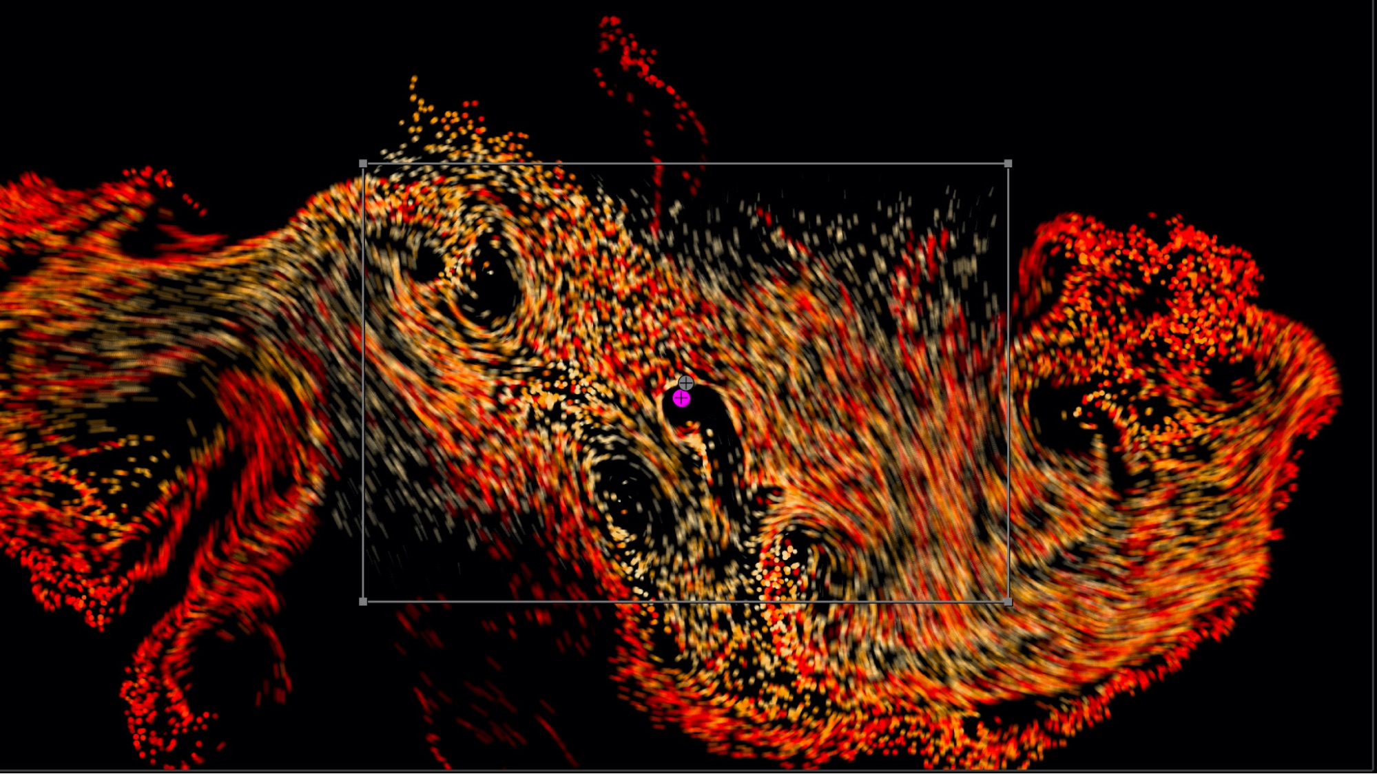
In 2D projects, the “Simulation Detail” parameter allows higher settings than in 3D projects. Like in 3D projects, higher settings may not always produce the best results, so experiment!
Standalone vs Plugin Mode
Although you’ll typically use Particle Illusion as a plugin applied to a layer in your host, it’s also possible to launch it as a standalone application. Only in standalone mode will you be able to modify the Project Settings.
Project Settings
The Project Settings Window allows for customization of the current project: Stage size, Duration, Frame Rate and other features. (When PI is launched from a host such as Adobe After Effects, many of these parameters are pulled directly from the host itself, and cannot be changed).
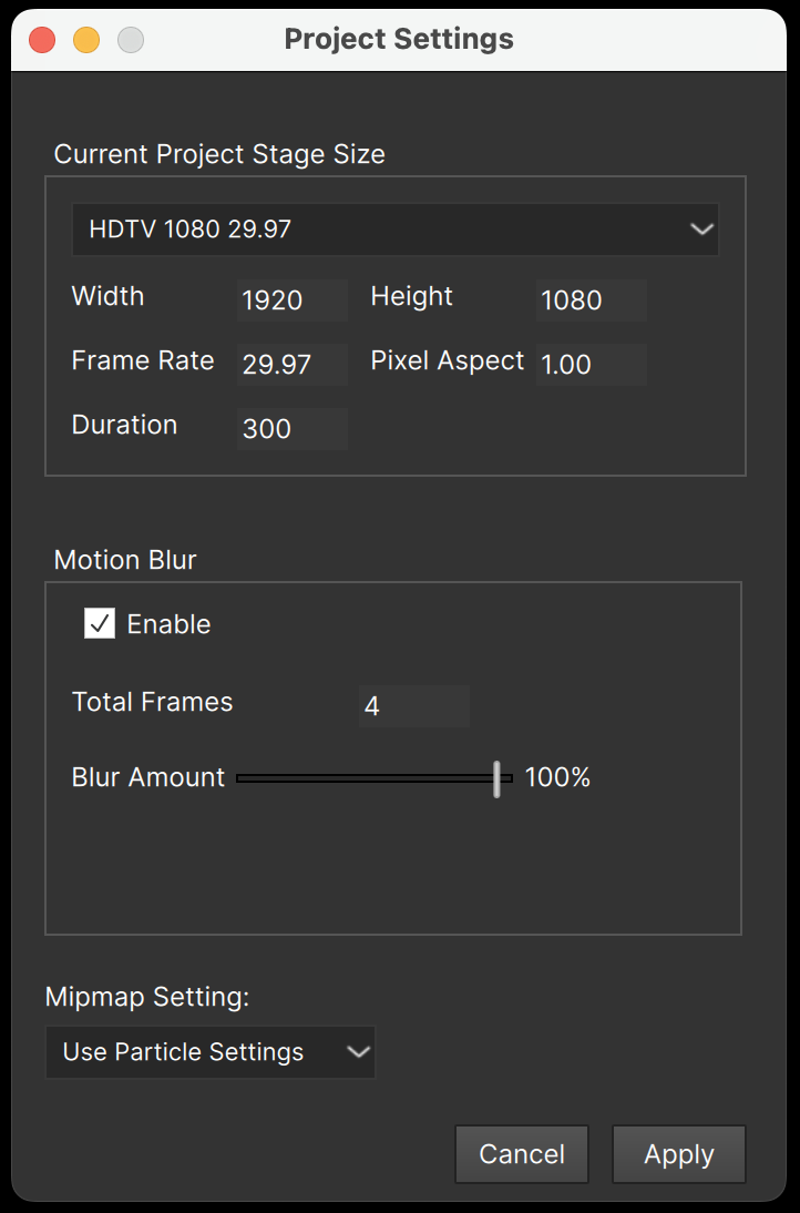
Motion Blur is a key feature that adds realism to many of the emitters, and when turned on in a project (using the “Enable” checkbox here or the “Stage – Motion Blur” menu) these are the settings used. You probably won’t want to change these values, but this is what they do:
- Total Frames. This sets the number of frames of motion blur to use. Note that motion blur requires multiple copies of each particle to be drawn, so although higher values result in smoother blurring, it takes longer to render. The default value of “4” is a good compromise between quality and performance.
- Blur Amount. The amount of the distance between frames that the blurring occurs. When set to 100% the particles are blurred the entire distance they would move between the two frames. When set to 50%, the blurring will occur in ½ the distance. (When set to 0% no blurring occurs.)
“Mipmap Setting” allows you to override the mipmapping settings contained in each particle type. The default setting is to use the settings contained in the emitter (set per particle type), but you can also force mipmapping on or off for all particles. (As a reminder, mipmapping uses resampled copies of the particle image shape texture for smaller sizes, which reduces aliasing — jagged edges — and can result in a higher-quality but “softer” render.)
Licensed vs. Unlicensed
When Particle Illusion is licensed (via Continuum license, BorisFX Suite license, or PI Pro license) you’ll have access to the full feature set.
When Particle Illusion is unlicensed, all core features are enabled – only the following features will not be available:
- Video Import
- Position Data Import
Also note that when unlicensed, Particle Illusion is for personal/non-commercial use only, and support is through the Particle Illusion user forum only.
If you’re unsure whether you’re licensed or not, the title bar will indicate “Particle Illusion Pro” when licensed, and “Particle Illusion” when unlicensed. (It will also indicate if you’re running as a plugin or standalone.)
The “Help” menu “About Particle Illusion…” box will also show this information.
Importing Video
A feature available only when licensed and running standalone is the ability to import video. The layer node will contain an empty grey thumbnail when this feature is available.
Either double-click the thumbnail on the layer node, select the layer node then click the “import video…” button, or r-click the layer node (or use the “Action” and select “Import Video”:
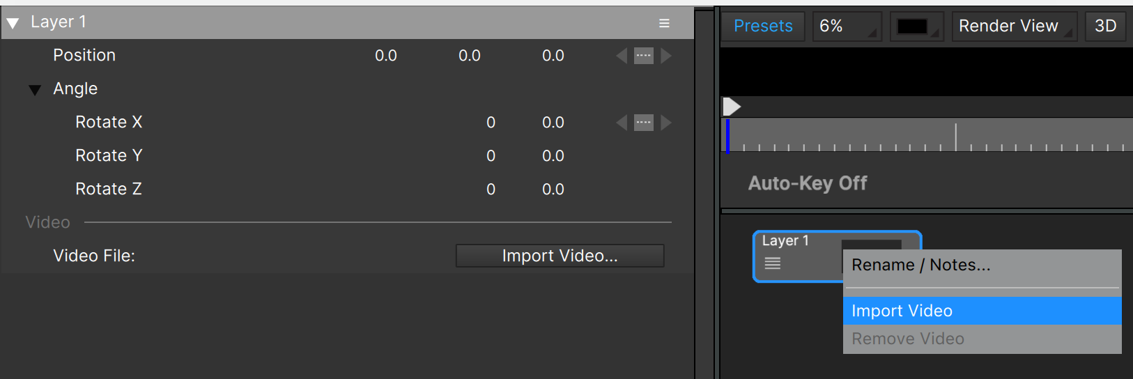
The supported video formats/file types are: avi, dv, m2v, mkv, mov, mp4, m4v, mpg, mts, m2ts, mxf, qt, wmv
Note that some formats (for example mxf) may not be fully supported.
If the video is of different dimensions than the PI project, you’ll be asked if you want to resize – the answer is almost always “yes” – and then the duration and framerate of the PI project will be changed to match the video if needed.
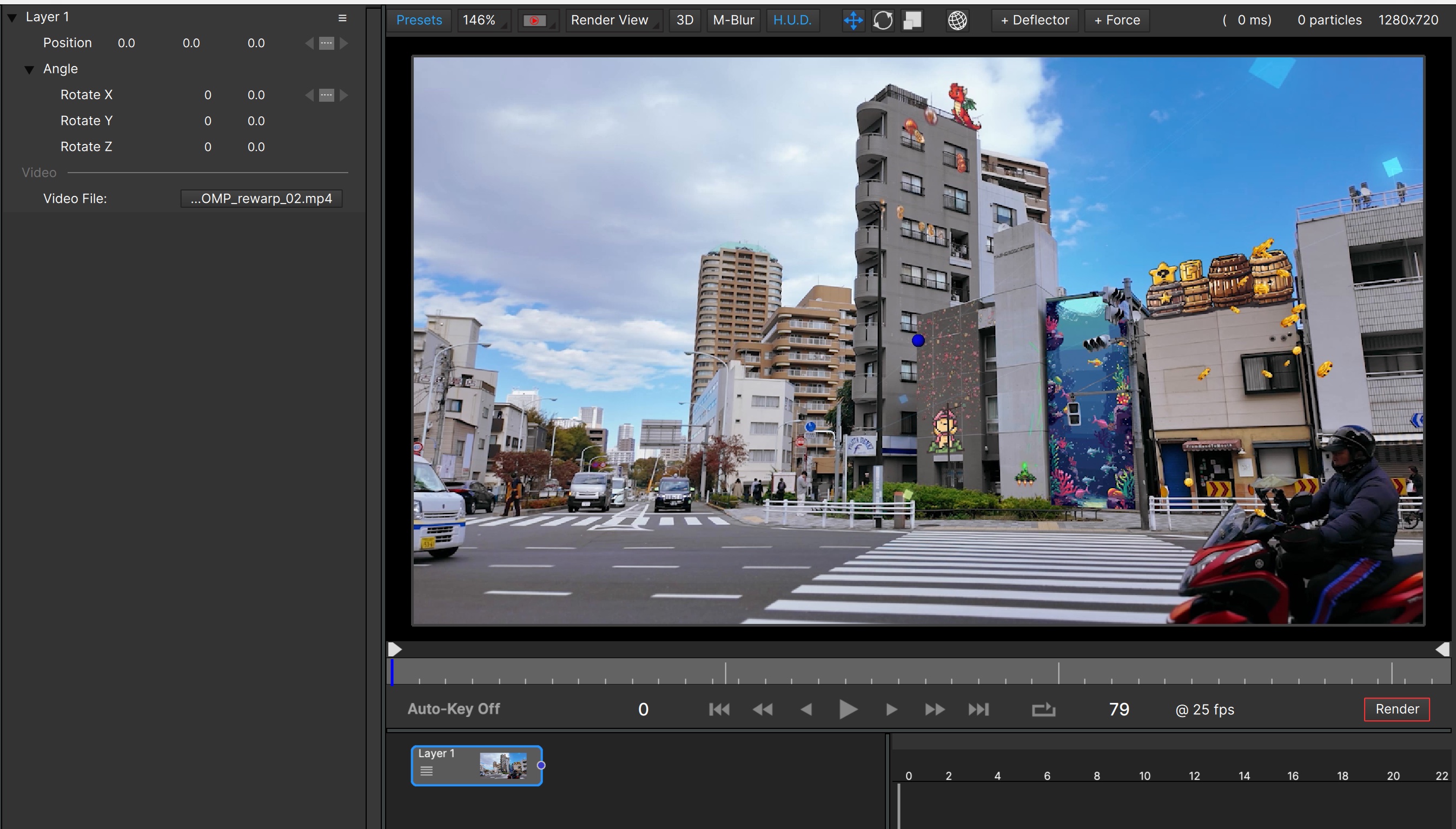
To remove a video, R-click the Layer node (or use the Layer Hamburger Menu, or the Application “Action” menu) and select “Remove Video”.
Note that it’s only possible to have a single layer in Particle Illusion currently, so only a single video is possible.
If the video contains audio, it will NOT be preserved in the final render (the render will not contain audio).
Importing Position Data
Another feature available only when licensed is the importing of position data from text files generated by Mocha Pro or SynthEyes. You can import position data for the PI camera or for any emitter in your project.
To import position data for the camera, use the camera hamburger menu and “Import Position Data”.
To import for an emitter, select the emitter node and R-click it (or use the hamburger menu) and “Import Position Data”.
In either case you’ll need to select a text file that was created by Mocha Pro or SynthEyes.
In Mocha Pro, choose the “After Effects Transform Data” format when exporting:
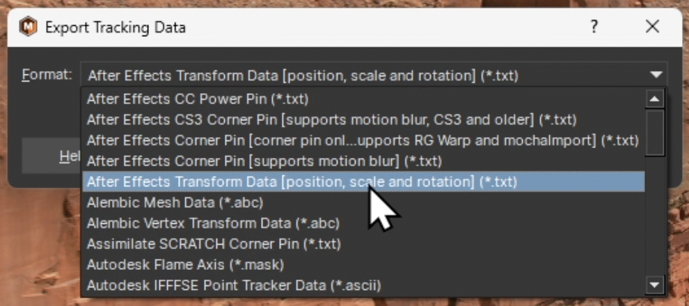
In SynthEyes, simply select the “Particle Illusion” format when exporting.
The Preferences Window
The Preferences “General” Panel is where you set the default project settings and other aspects of the application.
Set Stage Size (resolution), Pixel Aspect ratio, Duration, and Frame Rate here:
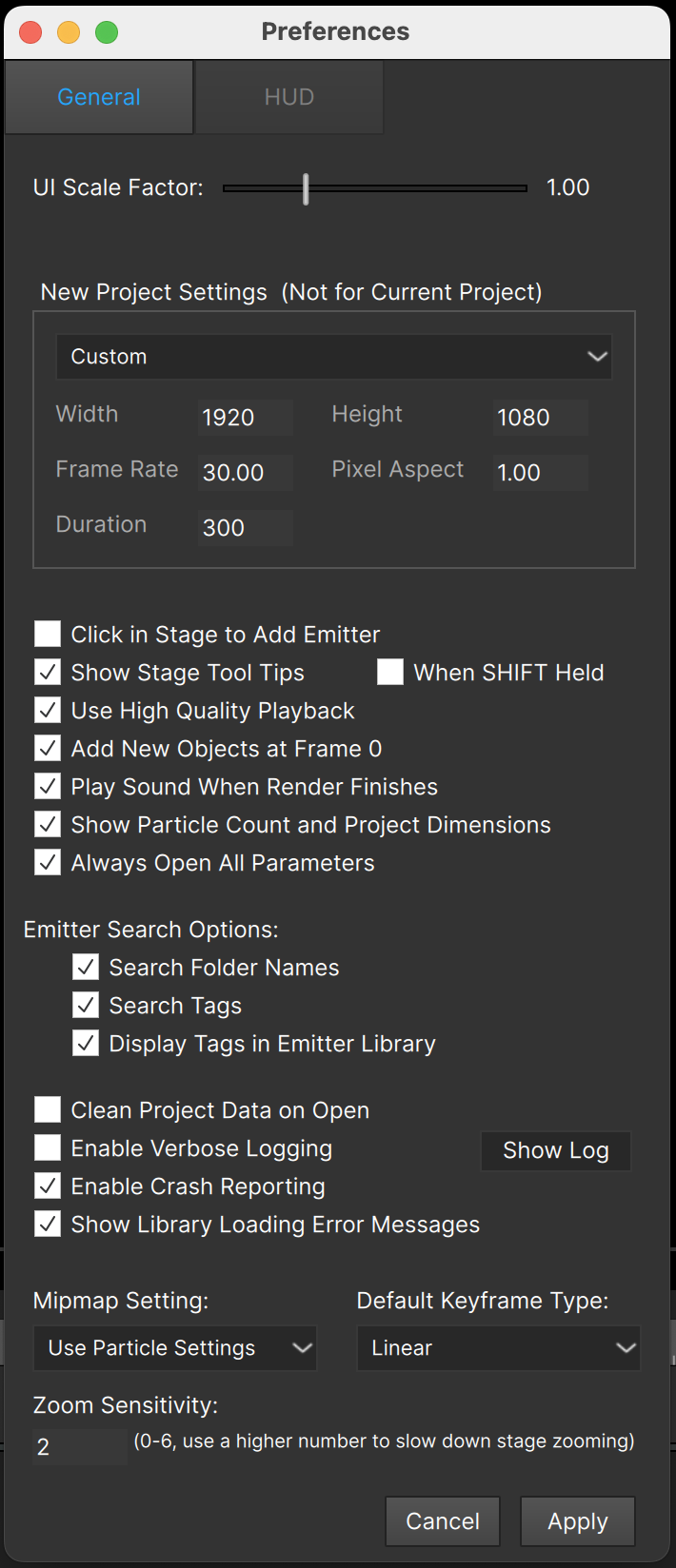
It’s important to realize that changing the Stage Size and other settings in the top part of this dialog does NOT change the current project — it only applies when a new project is created.
The preferences below the stage size section are application settings:
The “Click in Stage to Add Emitter” option can be unchecked if you find yourself accidentally adding new emitters to the Stage by clicking. Note that if you uncheck this option, the only way to add an emitter to the project will be to double-click its name in the Emitter Library Browser.
“Show Stage Tool Tips”: When checked, tooltips show in the Stage (Composite View) when the mouse cursor is over something that can be clicked or dragged:
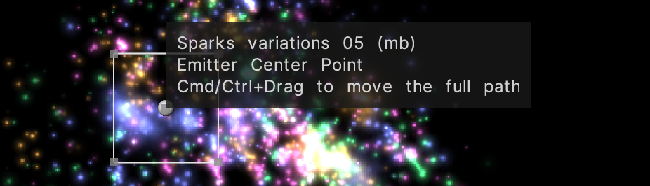
Although these tooltips can help you know what will be clicked — especially useful in projects that contain many overlapping emitters, forces, and deflectors — you may find them to be intrusive.
“When SHIFT Held” allows tooltips to be shown only when the SHIFT key is held – an easy way to toggle Stage tooltips on-demand. Note that this is only visible when “Show Stage Tool Tips” is checked.
“Use High-Quality Playback”: When checked particles are rendered to an offscreen buffer giving highest quality results. When unchecked, particles will render directly to the window, which can give a performance boost on some older hardware and OSes. Note that when motion blur is turned on this setting is ignored — particles are rendered to an offscreen buffer as if this setting were checked.
“Add New Emitters at Frame 0”: When checked an emitter is always added at frame 0. When unchecked, the emitter will be added at the current frame.
“Play Sound When Render Finishes”: when using the render feature (to save ProRes output for instance) a sound will play when the render completes if this is checked.
“Show Particle Count and Project Dimensions”: when checked this information is displayed above the Stage. Since the particle count is always updating, some users may find this distracting — you can turn this information off here.
“Always Open All Parameters”: when checked, all parameter groups will always open, which makes all parameters easily accessible. We do mean “always” – If you close a group then select another node, when you come back to this node the group will be open again. If you are using a relatively low screen resolution, you may want to uncheck this option and open the closed groups manually. (Note that some groups like “Properties” will always open by default regardless of this setting.)
The Emitter Search Options:
- “Search Folder Names”: the folders in each emitter library are included in search results. When this option is checked all emitters in that folder will be included in the results if the search term is in the folder name. (This is not usually desired so is unchecked by default.)
- “Search Tags”: If you want to search only on emitter names you can uncheck this option. (It is checked by default as there are many emitters with names that are not descriptive.)
- “Display Tags in emitter library”: when checked, each emitter’s tags will display after its name (only in Library View).
“Clean project data on open”: If you’ve done a lot of work with changing particle shapes in your emitters, or have added particle types, added and deleted emitters, etc., you may find that your PI project (or host project) has become unexpectedly large in size (larger than expected file, using much more memory than seem reasonable, etc.) If you have this preference enabled, using the “load” function to open a saved PI project file should remove any excess bloat from the file and get it back to optimal size.
“Enable Verbose Logging”: When checked, extra information is added to the Particle Illusion log file. This in theory will decrease performance, but in practice this slowdown is not noticeable. The extra information logged will help us diagnose any problems you may have.
The “Show Log” button will open the log file so you can view it. Note that if you contact support you will probably be asked for this file.
“Enable Crash Reporting”: When checked, anonymous crash reports are generated and uploaded. This is very helpful to us to increase the stability of Particle Illusion, so please do not disable this – or enable it when you have a repeatable scenario that causes crashes.
“Show Library Loading Error Messages”: When a library can’t be loaded by Particle Illusion (which usually means it was created in a newer version, or has been corrupted) an error message is displayed at startup (when loading libraries). You can disable these messages using this preference.
“Mipmap Setting” allows you to override the mipmapping settings contained in each particle type. The default setting is to use the settings contained in the emitter (set per particle type), but you can also force mipmapping on or off for all particles. (As a reminder, mipmapping uses resampled copies of the particle image shape texture for smaller sizes, which reduces aliasing — jagged edges — and can result in a higher-quality but “softer” render.)
“Default Keyframe Type”: determines if the keys created in the graph view and Stage are “Linear” or “Bezier” when created. This defaults to “Linear” but if you find that you mainly use Bezier keys, you may want to change it here.
“Zoom Sensitivity”: Input devices have different scrollwheel speeds — for instance a trackpad may be too sensitive to allow it to zoom the Stage in a controllable way. By increasing this value you can decrease the sensitivity of zooming in the Stage: lower values zoom faster, while higher values zoom more slowly.
HUD Settings
There is a second page of preferences to set the HUD and other UI colors:
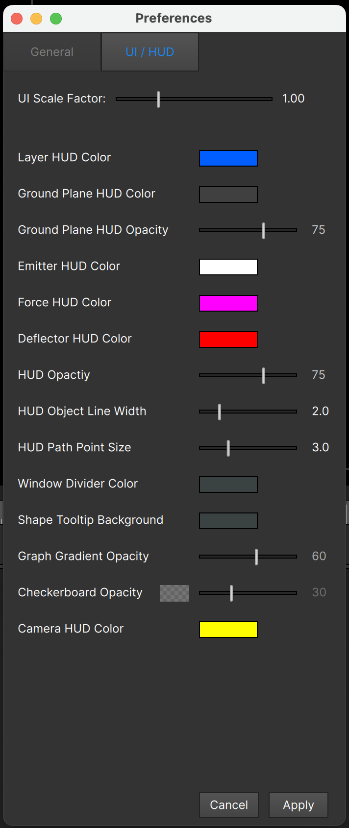
Here you can set the colors used for the Emitters, Deflectors, Forces, and Camera and the opacity of the HUD as well. In addition you can control:
- HUD Opacity. This slider controls all HUD objects including tooltips
- HUD Object Line Width. Set to a higher value to draw HUD objects with thicker lines for increased visiblity, or a lower value for a more unobtrusive, refined look.
- HUD Path Point Size. Controls the size of the position points, when an object’s position is animated. \
- Window Divider Color. If the dividers between the various views in the main PI interface are difficult to see, you can choose a different color here.
Note that if you are unable to see the HUD even when it is turned on, check these preferences to ensure that the Opacity has not inadvertently been set to a very low value. (Note that you will not be able to set this lower than 20 percent. If you want to turn off the HUD, use the HUD button above the stage.)
UI Scale Factor
There is a UI Scale Factor slider at the top of the Preferences pages. This can be used to scale all interface elements – if everything is a bit too small in PI, increase the UI Scale Factor slightly. If things are too large, decrease it. As indicated you will need to restart PI for the new value to take effect.
It’s recommended to make relatively small changes to this value especially if you’re decreasing it or you may end up with a PI interface that is quite difficult to read!
Note that this value doesn’t change your OS display settings or resolution and will only affect PI.
Resetting Preferences
In the event that Particle Illusion won’t start up, or the application starts but the UI window is not visible, the recommended action is to reset the preferences. This has previously been difficult, as it required you to locate the the file, delete it, and reboot (Mac) or edit the Registry (Windows). Starting in v2022.5, it’s easy:
To delete the preferences, just hold the SHIFT key when launching PI.
If successful, PI will open and you will see a message confirming the reset:
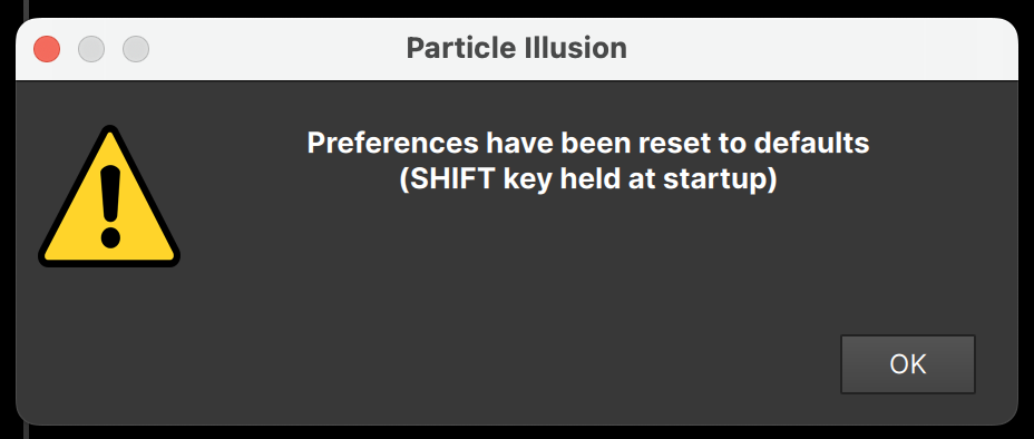
Note that resetting the prefs in this way will be indicated in your PI.log file, and the preferences values will be added to the log too.
PI.Log - Diagnostic Log File
Particle Illusion will write various kinds of data to a diagnostic log file. This is not usage data, but information that could be helpful to us when providing support.
Here is an example of the log file from a short Particle Illusion session:
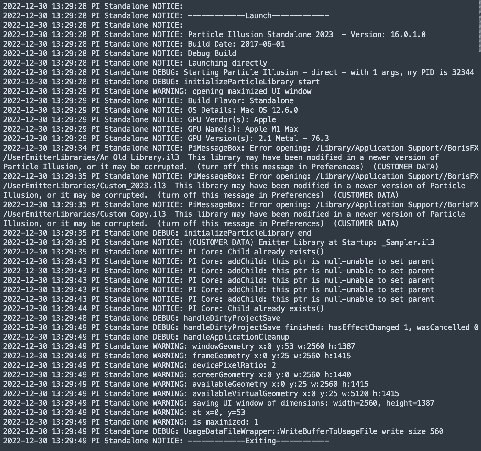
Note that most of the data in the PI.log file is generic/anonymous, except for cases where a filename or path error message is logged. Since those items may contain sensitive information, they have been flagged with the label “(CUSTOMER DATA)”. This has been done so you can search the log file for that string to see if there is anything you might want to remove or edit before sending to us.
Remember that you can easily view the log file using the “Help - View Log File” menu.
(The newest data is found at the bottom of the file.)
File Locations
Here is a handy reference list of all important folders and files used by Particle Illusion.
Mac
/Users/<your user name/Library/Logs/BorisFX/PI.Log
The diagnostic log file for Particle Illusion (see above section).
/Library/Application Support/BorisFX/EmitterLibraries
All of the locked (factory) emitter libraries, except for _Sampler.il3 (which is stored in the Particle Illusion app bundle as a resource).
/Library/Application Support/BorisFX/UserEmitterLibraries
The unlocked emitter libraries, including Custom.il3. You can copy/move any of the locked emitter libraries into this folder.
/Library/Application Support/BorisFX/PI3DModels
The 3D Models used in Emitter Libraries. The factory-installed models include the prefix “BFX_”. If you add an emitter that uses a 3D model to a library, the model file will be copied here.
/Library/Application Support/BorisFX/PIFactoryPresets
Color gradient, alpha gradient, and over life graph factory presets. There is no need to back up or modify these files.
/Library/Application Support/BorisFX/PIFactoryPresets/Camera_Presets
The factory camera presets. There is no need to back up or modify these files.
/Users/<your user name/Library/Application Support/BorisFX
Contains the following files:PIFavoriteEmitters.json - your “Favorite” emitters listPIColorGradientPresets.dat - your working set of color gradient presets, custom plus factoryPIAlphaGradientPresets.dat - your working set of alpha gradient presets, custom plus factoryPIOverLifeGraphPresets.dat - your working set of over life graph presets, custom plus factory
/Users/<your user name/Library/Application Support/BorisFX/PIUserCameraPresets
Contains any camera presets that you saved yourself.
Windows
C:\Users\<your user name>\AppData\Local\BorisFX\Particle_Illusion\PI.log
The diagnostic log file for Particle Illusion 2024.5 or newer.
C:\Users\<your user name>\AppData\Roaming\BorisFX\Logs\PI.log
The diagnostic log file for Particle Illusion 2024.0 or older.
C:\ProgramData\BorisFX\EmitterLibraries
All of the locked (factory) emitter libraries, except for _Sampler.il3 (which is stored in the Particle Illusion program files folder).
C:\ProgramData\BorisFX\UserEmitterLibraries
The unlocked emitter libraries, including Custom.il3. You can copy/move any of the locked emitter libraries into this folder.
C:\ProgramData\BorisFX\PI3DModels
The 3D Models used in Emitter Libraries. The factory-installed models include the prefix “BFX_”. If you add an emitter that uses a 3D model to a library, the model file will be copied here.
C:\ProgramData\BorisFX\PIFactoryPresets
Color gradient, alpha gradient, and over life graph factory presets. There is no need to back up or modify these files.
C:\ProgramData\BorisFX\PIFactoryPresets\Camera_Presets
The factory camera presets. There is no need to back up or modify these files.
C:\Users\<your user name>\AppData\Local\BorisFX
Contains the following files:PIFavoriteEmitters.json - your “Favorite” emitters listPIColorGradientPresets.dat - your working set of color gradient presets, custom plus factoryPIAlphaGradientPresets.dat - your working set of alpha gradient presets, custom plus factoryPIOverLifeGraphPresets.dat - your working set of over life graph presets, custom plus factory
C:\Users\<your user name>\AppData\Local\BorisFX\PIUserCameraPresets
Contains any camera presets that you saved yourself.
One last thing to note:
C:\Users\<your user name>\AppData\Local\BorisFX\Particle_Illusion\cache
This is a small amount of cached data related to the UI – do not modify or delete! (It has nothing to do with particle data caching).
Keyboard Shortcuts
Spacebar Toggle Playback
PgUp or L arrow Previous Frame
PgDn or R arrow Next Frame
Shift+L arrow Jump 10 frames back
Shift+R arrow Jump 10 frames forward
Home Jump to first frame
End Jump to last frame
Mousewheel Zoom Stage (when cursor over Stage)
F Zoom Stage to Fit
Cmd B/Ctrl+B Toggle Motion Blur in Stage
delete/backspace Stage: delete selected object
delete/backspace Graph View: delete selected keys
delete/backspace Emitter Library Browser: remove the selected emitter from library (if unlocked)
Cmd/Ctrl+T Update selected library emitter thumbnail from preview (if library unlocked)
Enter/Return Emitter Library Browser: rename the selected library emitter (if unlocked)
Cmd/Ctrl+1 Load the Default View Layout (all views visible in default sizes)
Cmd/Ctrl+2 Load the “Edit” View Layout (hides Emitter Library Browser and Preview)
Cmd/Ctrl+3 Load the “Create” View Layout
Cmd/Ctrl+4 Load the “Browse” View Layout (only Emitter Library Browser and Preview visible)
Cmd/Ctrl+S Save Project (using current file name)
Shift Cmd/Ctrl+S Save Project As (with a new file name)
Cmd/Ctrl+O Open Project
Cmd/Ctrl+N New Project
Cmd/Ctrl+Z Undo
Shift Cmd/Ctrl+Z Redo
Alt Shift Ctrl+P Load the most recently saved project (Windows)
Opt Shift Cmd+P Load the most recently saved project (Mac)
Cmd/Ctrl drag an emitter or force in the Stage to move the entire position path (when position is animated)
Option/Alt click on a position key in the Stage to toggle between Linear and Bezier.
Option/Alt click on a bezier handle in the Stage to disconnect from the other handle (disconnected handles move independently of each other). Option/Alt click on either disconnected handle to connect them again.
Cmd/Ctrl drag the start frame handle of an emitter, deflector, or force to change the active frame without moving any keyframes.
Option/Alt click on a deflector or line emitter segment to add a point.
Option/Alt click on the last deflector or line emitter point to enter “add points” mode – each click will add another point until double-click or ESC.
Shift+drag CTI, Start Frame Bar, or In/Out markers to jump by 5 frames
Option/Alt double-click a node icon to solo/unsolo it.
Click and hold on a node icon to temporarily solo while held.
Click and hold on a node sprite image to see a larger version of the image.
Option/Alt-drag a node color gradient, alpha gradient, or particle image between particle nodes.
Double-click a parameter name to emphasize (or remove the emphasis)
Option/Alt double-click a parameter name to link it (or unlink)
(end of document)